6
Temposonics
®
ET Analog ATEX / IECEx / CEC / NEC / CCC Certified
Operation Manual
3. Identification
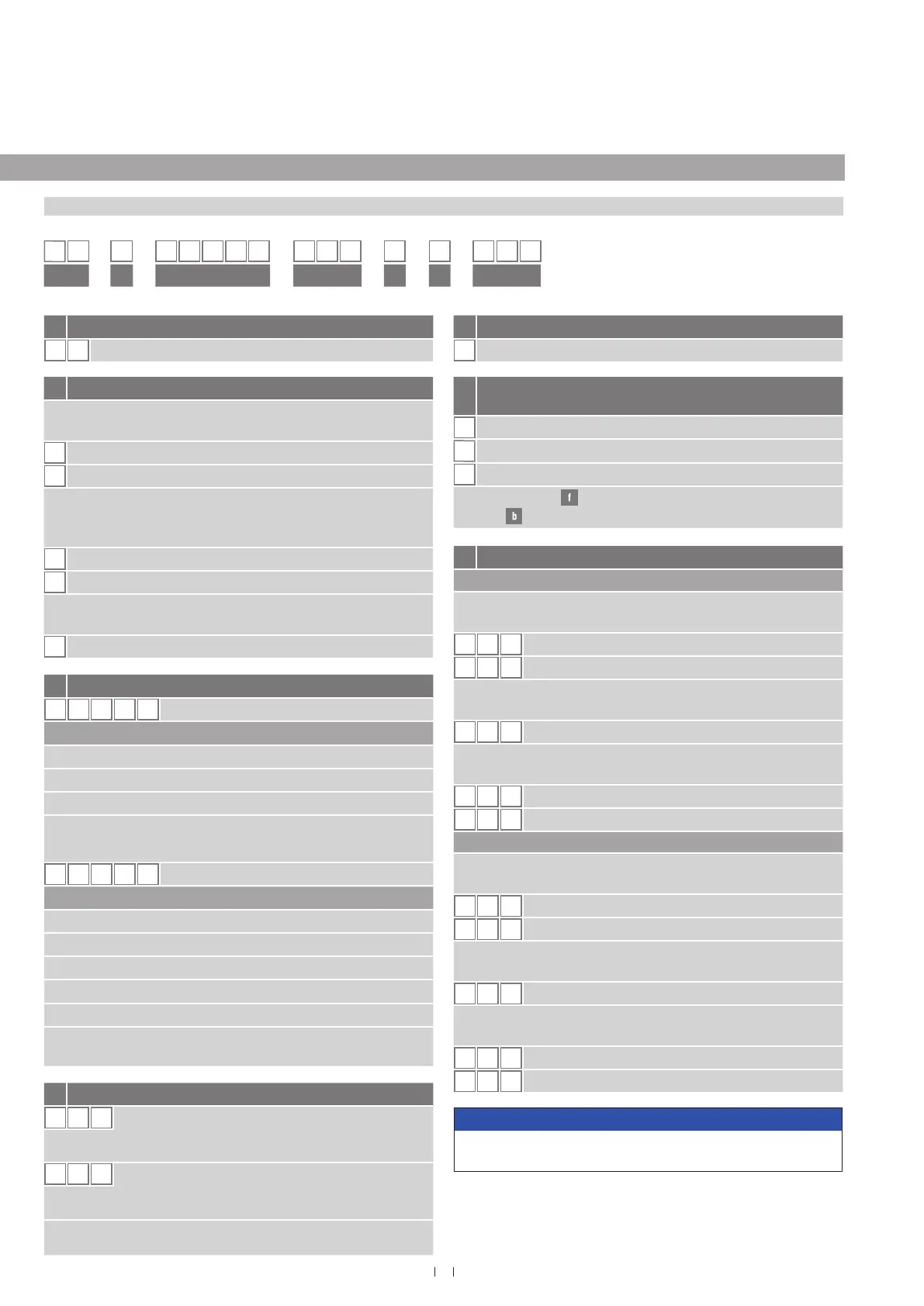
3.1 Order code Temposonics
®
ET
c Stroke length
X X X X M
0050…3000 mm
Standard stroke length (mm) Ordering steps
50… 500 mm 5 mm
500… 750 mm 10 mm
750…1000 mm 25 mm
1000
…
2500 mm 50 mm
2500…3000 mm 100 mm
X X X X
U
002.0…118.0 in.
Standard stroke length (in.) Ordering steps
2… 20 in. 0.2 in.
20… 30 in. 0.5 in.
30… 40 in. 1.0 in.
40…100 in. 2.0 in.
100…116 in. 4.0 in.
Non-standard stroke lengths are available;
must be encoded in 5 mm / 0.1 in. increments
.
a Sensor model
E T
Rod/Profi le
b Design
ET rod-style sensor with housing and sensor rod material
stainless steel 1.4404 (AISI 316L)
F
Threaded fl ange ¾"-16 UNF-3A
W
Threaded fl ange M18×1.5-6g
ET rod-style sensor with housing material stainless steel
1.4305 (AISI 303) and sensor rod material stainless steel
1.4306 (AISI 304L)
M
Threaded fl ange M18×1.5-6g
S
Threaded fl ange ¾"-16 UNF-3A
ET profi le-style sensor with housing material stainless steel
1.4305 (AISI 303) and profi le material aluminium
P
Profi le
e Operating voltage
1
+24 VDC (−15/+20 %)
1 2 3 4 5 6 7 8 9 10 11 12 13 14 15 16
E
T
1
a b c d e f g
d Connection type
T X X
XX m Tefl on
®
cable (part no. 530 112)
T01…T30 (1…30 m/3…99 ft.)*
See “Frequently ordered accessories” for cable specifi cations
V X X
XX m silicone cable (part no. 530 113)
V01…V30 (1…30 m/3…99 ft.)*
See “Frequently ordered accessories” for cable specifi cations
*/ Encode in meters if using metric stroke length.
Encode in feet if using US customary stroke length
Voltage
1 output with 1 position magnet
Output 1 (position magnet 1)
V 0 1
0…10 VDC
V
1 1
10…0 VDC
2 outputs with 1 position magnet
Output 1 (position magnet 1) + output 2 (position magnet 1)
V 0 3
0…10 VDC 10…0 VDC
2 outputs with 2 position magnets
Output 1 (position magnet 1) + output 2 (position magnet 2)
V 0 2
0…10 VDC 0…10 VDC
V 1 2
10…0 VDC 10…0 VDC
Current
1 output with 1 position magnet
Output 1 (position magnet 1)
A 0 1
4…20 mA
A
1 1
20…4 mA
2 outputs with 1 position magnet
Output 1 (position magnet 1) + output 2 (position magnet 1)
A 0 3
4…20 mA 20…4 mA
2 outputs with 2 position magnets
Output 1 (position magnet 1) + output 2 (position magnet 2)
A 0 2
4…20 mA 4…20 mA
A 1 2
20…4 mA 20…4 mA
NOTICE
Use magnets of the same type for multi-position measurement,
e.g. 2 × U-magnet (part no. 251 416-2 ).
f
Version (see “Certifi cation of Temposonics
®
ET (version A and
E)” on page 25 for further information)
A
ATEX / IECEx / CEC / NEC / CCC
E
ATEX / IECEx / CEC / NEC / CCC with ½" NPT adapter
N
Not approved
Version E (section
) is only available with design »M« and »S«
(section
) .

 Loading...


