23
Temposonics
®
ET Analog ATEX / IECEx / CEC / NEC / CCC Certified
Operation Manual
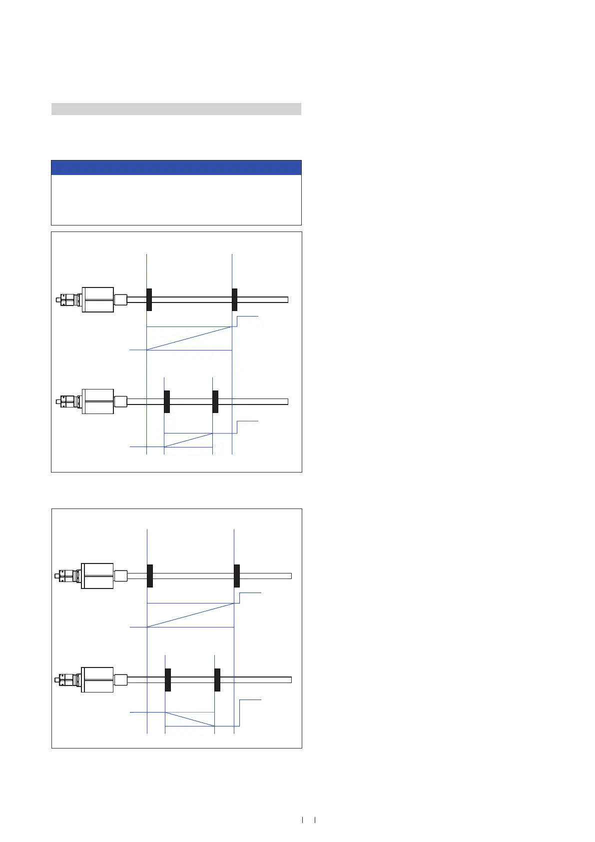
5.2.4 Setting examples for programming tools
The sensor‘s measuring range can be repositioned within the active
measuring range using the tools described above at any time.
NOTICE
Independent of the measuring direction, the location of the setpoints
in the factory settings is always: SP1 (set point 1) at sensor
electronics housing and SP2 (set point 2) at rod end. (Fig. 37 + Fig.
38).
Fig. 37: Adjust start and end position
Fig. 38: Start and end position, adjustment / reversal of measuring direction
SP1
SP2
20 mA
20 mA
4 mA
4 mA
0 %
SP1
100 %
SP2
Factory setup
Output: 4…20 mA
New field setting
Output: 4…20 mA
Active measuring range
SP1
SP2
20 mA
4 mA
4 mA
20 mA
0 %
SP1
100 %
SP2
Factory setup
Output: 4…20 mA
New field setting
Output: 20…4 mA
Active measuring range
 Loading...


