19
Temposonics
®
ET Analog ATEX / IECEx / CEC / NEC / CCC Certified
Operation Manual
5.2.2 Analog cabinet programmer, part no. 253 408
Install the built-in programming unit firmly in the control cabinet. It is
possible to change the start and end positions as well as the measur-
ing direction via simple teach in process, see also “5.2.4 Setting ex-
amples for programming tools” on page 23. After that, the changed
parameters are stored in the sensor. Move the position magnet to the
desired start or end position and push the corresponding “0 %” or
“100 %” button on the hand programmer. The minimum distance be-
tween the new setpoints is 25 mm (1 in.). The individual steps are ex-
plained in the following section.
Fig. 27: Active measuring range
The cabinet programmer is designed for mounting on standard 35 mm
(1.38 in.) rails according to DIN EN 60715 / 50022. Install the cabi-
net programmer between sensor and controller e.g. in a control cab-
inet. Using the cabinet programmer the sensor can be easily re-pro-
grammed as needed with no additional tools.
Step 1: Install cabinet programmer
Step 2: Connect cabinet programmer
Step 3: Adjust measuring range
Fig. 28: Dimensions: 10 × 55 × 31 mm (0.39 × 2.17 × 1.22 in.); material: Aluminum, side
caps PA 6.6 FR; connection type: Spring terminals, max. 1,5 mm
2
; ingress protection: IP20
Step 1: Install cabinet programmer
Step 2: Connect cabinet programmer
Step 3: Adjust measuring range
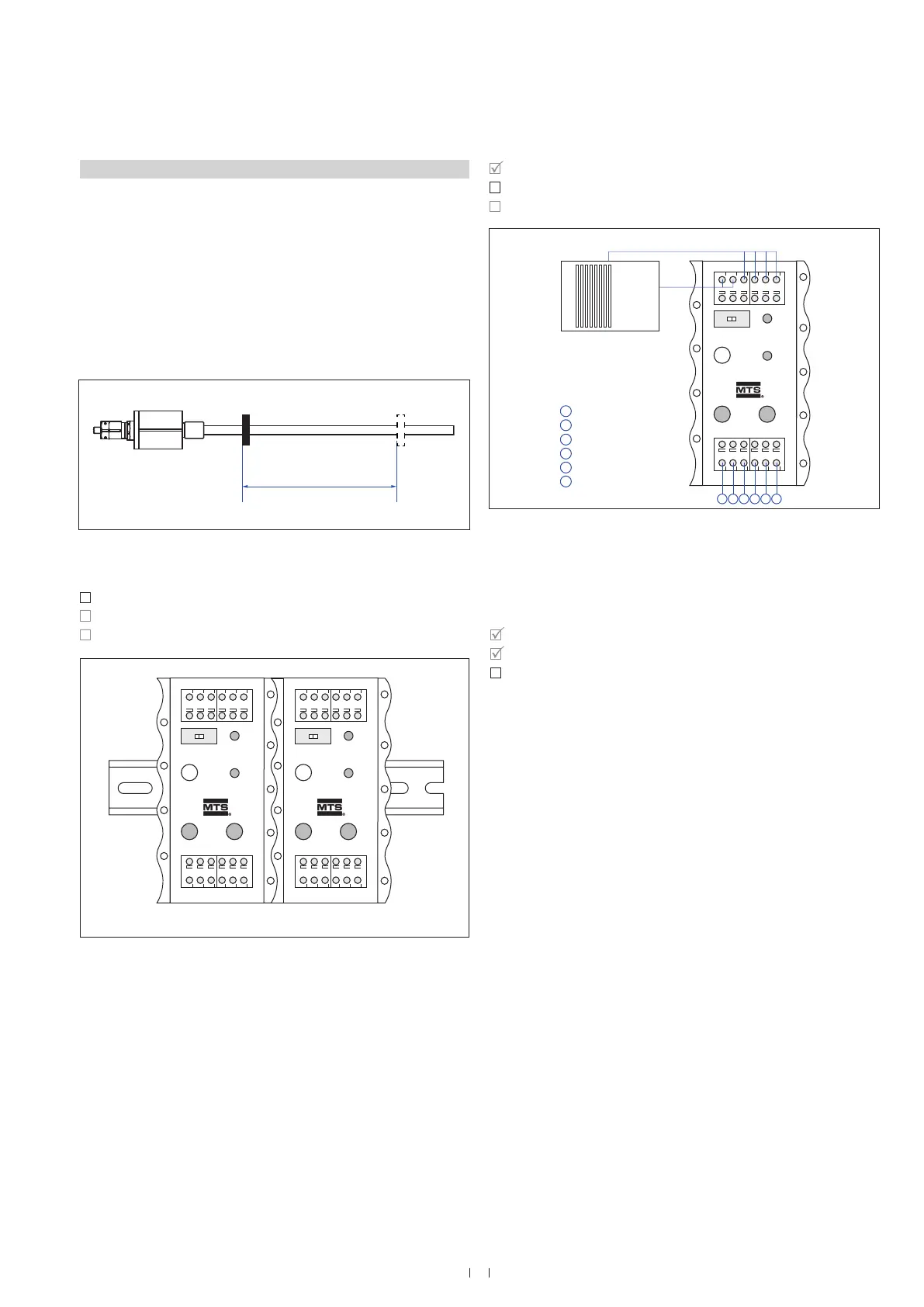
Connect the cabinet programmer to the controller, to the power supply
and to the sensor according to Fig. 29.
Fig. 29: Connect cabinet programmer (see connector wiring Fig. 21)
1. Activate programming mode:
• Slide switch to “Program”
• Press “Start” button and “100 %” button simultaneously
• Release “Start” button first, wait 1 second and release
“100 %” button
• Green “Programming mode” LED on cabinet programmer flashes
(programming mode reached)
Point 2 – 4 on the next page
Step 1: Install cabinet programmer
Step 2: Connect cabinet programmer
Step 3: Adjust measuring range
Active measuring range
Stroke length
0 % 100 %Magnet position
Output 1: Position
Sensor 1 Sensor 2
PLCSENSOR
Program /Run
Start
0 %
100 %
Programming mode
24 VDC
PLCSENSOR
Program /Run
Start
0 %
100 %
Programming mode
24 VDC
PLCSENSOR
Program /Run
Start
0 %
100 %
Programming mode
24 VDC
Out 1 / Pin 1, GY
GND 1 / Pin 2, PK
Out 2 / Pin 3, YE
GND 2 / Pin 4, GN
24 VDC / Pin 5, BN
GND / Pin 6, WH
123456
1
2
3
4
5
6
Analog input module
Power supply

 Loading...


