20
Temposonics
®
ET Analog ATEX / IECEx / CEC / NEC / CCC Certified
Operation Manual
Fig. 30: Determine start and end position
2. Set start position (0 % output) (Fig. 30):
• Set the position magnet to start position
• Press and release the “0 %” button
3. Set end position (100 % output) (Fig. 30):
• Set the position magnet to end position
• Press and release the “100 %” button
4. Back to normal function (operation mode):
• Press and release the “Start” button
• LED “Programming mode” stops flashing
• Slide switch to “Run”
• Green LED “24 VDC” shows normal function
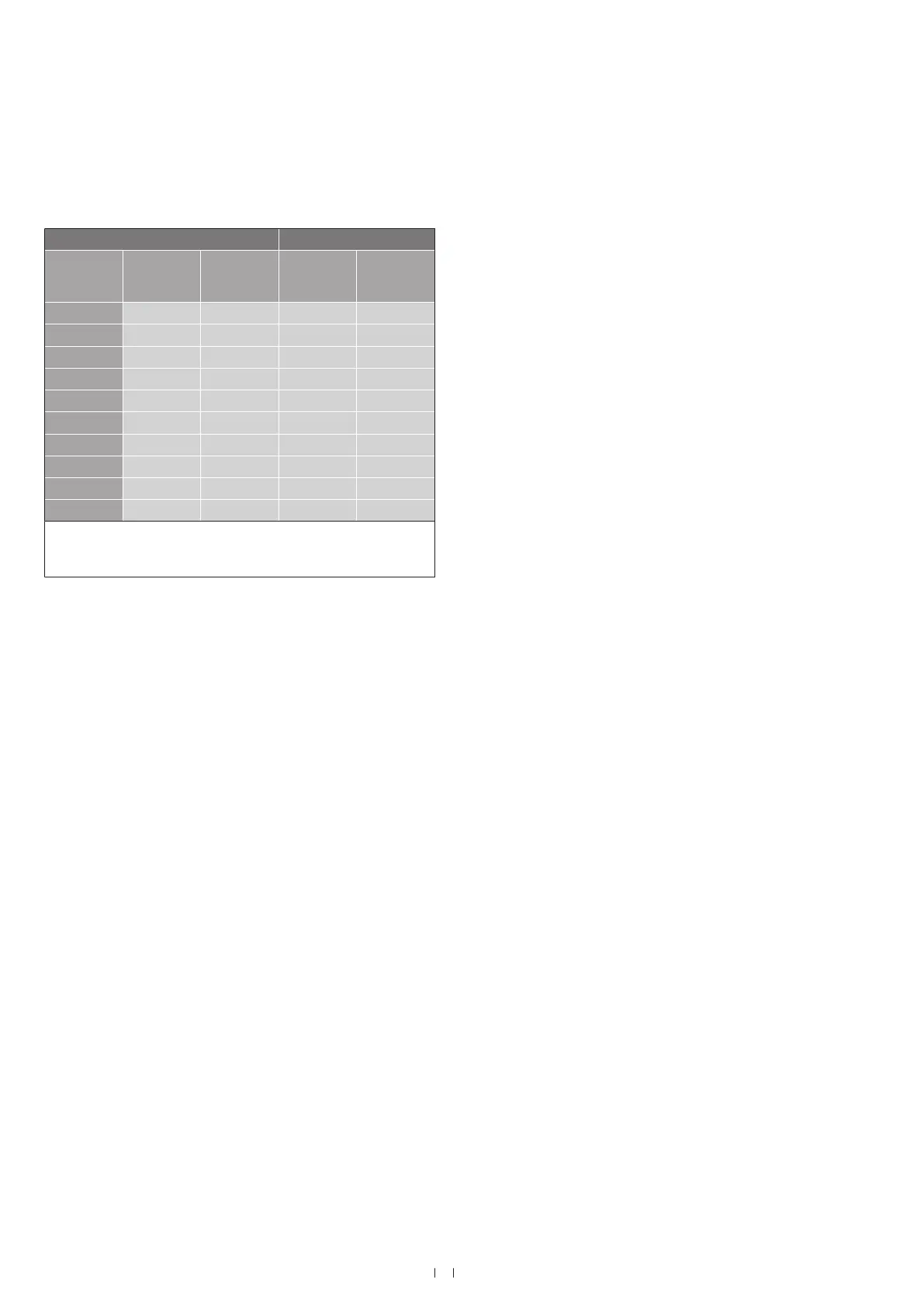
Output 1 Output 2
Output from
order code
Start posi-
tion (0 %
output)
End positi-
on (100 %
output)
Start posi-
tion (0 %
output)
End positi-
on (100 %
output)
V01 0 VDC 10 VDC — —
V11 10 VDC 0 VDC — —
V03 0 VDC 10 VDC 10 VDC 0 VDC
V02 0 VDC 10 VDC 0 VDC * 10 VDC *
V12 10 VDC 0 VDC 10 VDC * 0 VDC *
A01 4 mA 20 mA — —
A11 20 mA 4 mA — —
A03 4 mA 20 mA 20 mA 4 mA
A02 4 mA 20 mA 4 mA * 20 mA *
A12 20 mA 4 mA 20 mA * 4 mA *
* When using the analog hand programmer only the start and end
positions of magnet 1 (output 1) are adjusted. The settings of
magnet 2 (output 2) are not affected.

 Loading...


