8
Temposonics
®
ET Analog ATEX / IECEx / CEC / NEC / CCC Certified
Operation Manual
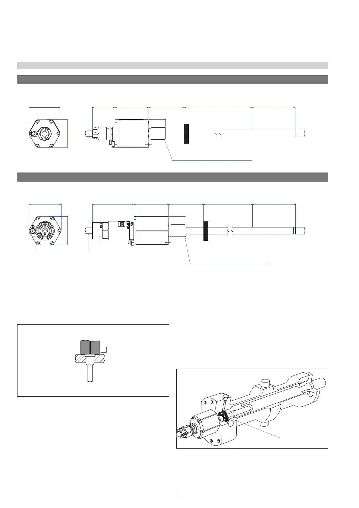
Fig. 4: Temposonics
®
ET (rod sensor) with ring magnet
4.2 Styles and installation of Temposonics
®
ET (rod sensor)
Installation of ET with threaded flange »F«, »M«, »S« & »W«
Fix the sensor rod via threaded flange M18×1.5-6g or ¾"-16 UNF-3A.
Lightly oil the thread before tightening.
Fig. 5: Mounting example of threaded flange »F«, »M«, »S«, »W«
Installation of a rod-style sensor in a fluid cylinder
The rod-style version has been developed for direct stroke
measurement in a fluid cylinder. Mount the sensor via threaded flange
or a hex nut.
• Mounted on the face of the piston, the position magnet travels
over the rod without touching it and indicates the exact position
through the rod wall – independent of the hydraulic fluid.
• The pressure resistant sensor rod is installed into a bore in the
piston rod.
Fig. 6: Sensor in cylinder
75 Nm
Position magnet
ET-F / -M / -S / -W, example: Version A / N
Threaded flange »M« / »W«: M18×1.5-6g
Threaded flange »F« / »S«: ¾"-16 UNF-3A
Null zone
51
(2)
25
(1)
Dead zone
63.5
(2.5)
Stroke length
50…3000
(2…118)
~34
(~1.34)
Sensor electronics
housing
50
(1.97)
Ø 10 ± 0.13
(Ø 0.39 ± 0.01)
Teflon
®
cable: Ø 7.6 (Ø 0.3)
Silicone cable: Ø 7.2 (Ø 0.28)
Magnet
41
(1.61)
47
(1.85)
A/F 41
M4×8 (ISO 1207)
Fastening torque: 2.5 Nm
ET-F / -M / -S / -W, example: Version E
Teflon
®
cable: Ø 7.6 (Ø 0.3)
Silicone cable: Ø 7.2 (Ø 0.28)
Threaded flange »M« / »W«: M18×1.5-6g
Threaded flange »F« / »S«: ¾"-16 UNF-3A
Ø 10 ± 0.13
(Ø 0.39 ± 0.01)
41
(1.61)
47
(1.85)
M4×8 (ISO 1207)
Fastening torque: 2.5 Nm
Magnet
~60
(~2.36)
housing
50
(1.97)
Null zone
51
(2)
A/F 41
Stroke length
50…3000
(2…118)
Dead zone
63.5
(2.5)
25
(1)
½"-14 NPT (inside)
Ø 24
(Ø 0.94)
Ø 27
(Ø 1.06)
Controlling design dimensions are in millimeters and measurements in ( ) are in inches

 Loading...


