18
Temposonics
®
ET Analog ATEX / IECEx / CEC / NEC / CCC Certified
Operation Manual
NOTICE
You can only adapt magnet 1 via hand programmer. In order to
change the settings of magnet 1 you have to connect both outputs
(output 1 and output 2).
Step 1: Connect hand programmer
Step 2: Adjust measuring range
1. Activate programming mode:
• Press “Start” button and “100 %” button simultaneously
• Release “Start” button first, wait 1 second and release
“100 %” button
2. Set start position (0 % output) (Fig. 26):
• Set the position magnet on start position
• Press and release the “0 %” button
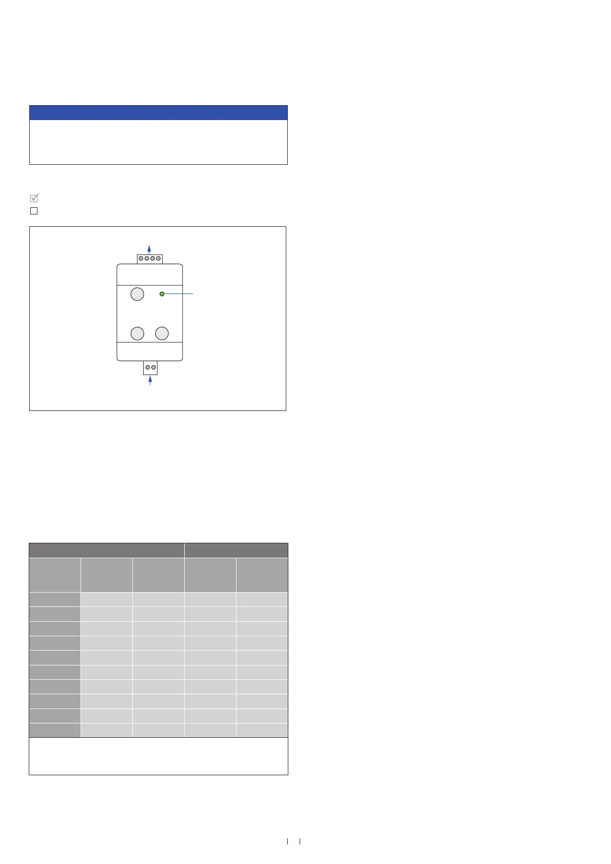
Fig. 25: Adjust measuring range
Fig. 26: Determine start and end position
3. Set end position (100 % output) (Fig. 267):
• Set the position magnet on end position
• Press and release the “100 %” button
4. Back to normal function (operation mode):
• Press “Start” button
• Connect the sensor to control unit
Start
0 %
100 %
LED
Output 1 Output 2
Output from
order code
Start posi-
tion (0 %
output)
End positi-
on (100 %
output)
Start posi-
tion (0 %
output)
End positi-
on (100 %
output)
V01 0 VDC 10 VDC — —
V11 10 VDC 0 VDC — —
V03 0 VDC 10 VDC 10 VDC 0 VDC
V02 0 VDC 10 VDC 0 VDC * 10 VDC *
V12 10 VDC 0 VDC 10 VDC * 0 VDC *
A01 4 mA 20 mA — —
A11 20 mA 4 mA — —
A03 4 mA 20 mA 20 mA 4 mA
A02 4 mA 20 mA 4 mA * 20 mA *
A12 20 mA 4 mA 20 mA * 4 mA *
* When using the analog hand programmer only the start and end
positions of magnet 1 (output 1) are adjusted. The settings of
magnet 2 (output 2) are not affected.
 Loading...


