MI.NET MULTI-NETWORK COLLECTOR
44
Installation and Operation Manual
TROUBLESHOOTING GUIDE
Caution must be used as hazardous voltage levels exist within the MNC.
SECTION 1, Power Section:
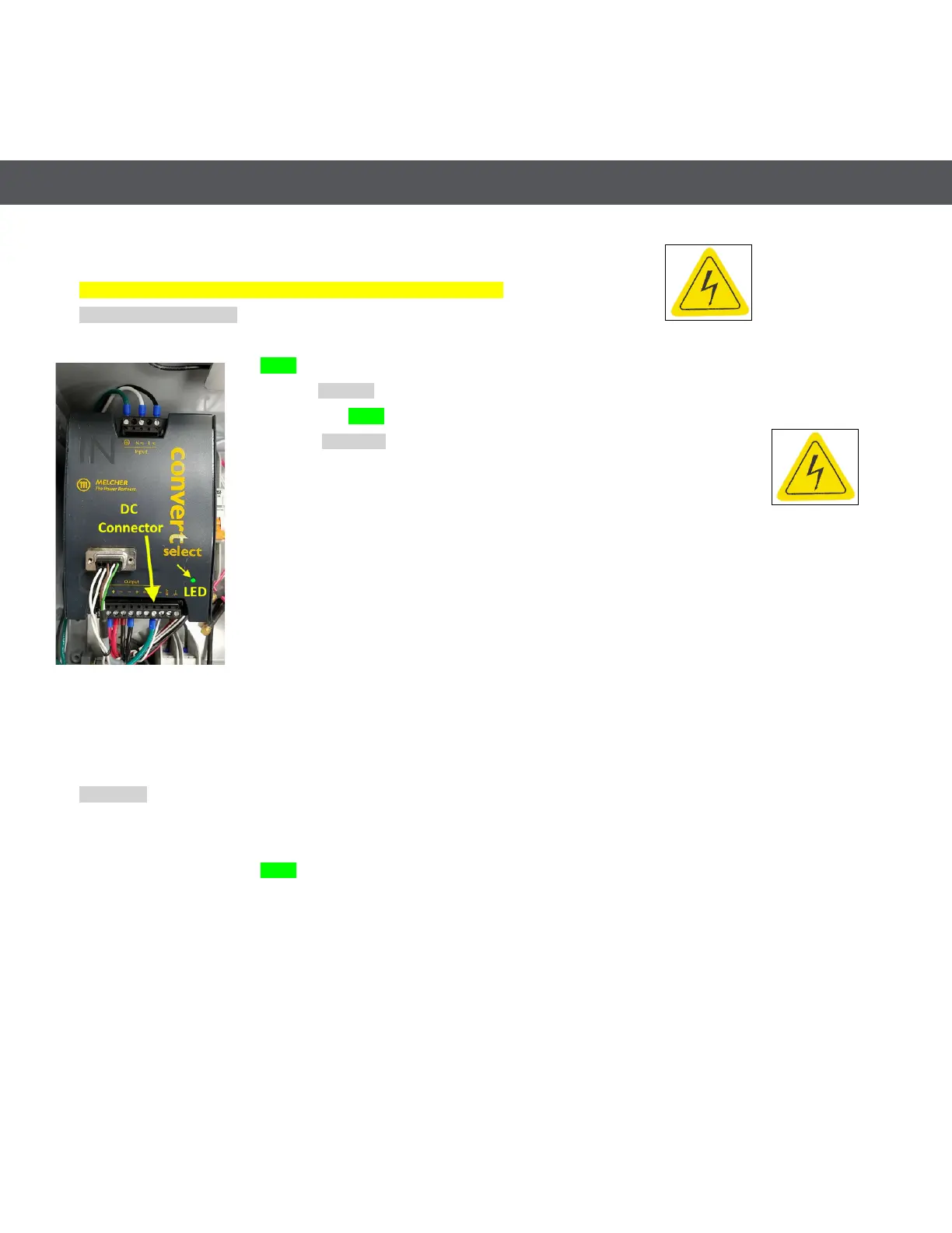
Temporarily turn off the Battery Circuit Breaker (down position, see Figure A6-1)
Is Green Status 1 LED on gateway illuminated?
Yes-> Go to Section 2
No-> Is Green LED on Power Supply illuminated?
Yes -> Go to Section 1B
No -> Check AC circuit breaker is ON (up position)
Check all AC Mains wires are properly attached to MNC terminals
Wiring OK?
No -> Repair wiring (refer to wiring diagram in Appendix VI)
Yes-> Is AC voltage present at AC terminals? (use AC voltmeter) *
No-> Check all AC wiring entering the Collector
Yes-> Is AC voltage present at top terminals of AC circuit breaker? (use AC voltmeter) *
No-> Replace AC Surge Protection Module, MS-RC-HUB-SA
Yes -> Check for AC voltage at power supply terminals at top of power supply (use AC voltmeter) *
AC present?
No -> Check wiring and/or replace AC Circuit Breaker, MS-RC-HUB-AB
Section 1B:
Yes -> Check for 13 - 15 VDC at power supply DC Connector, on 12V +/- pins
Voltage OK?
Yes -> Temporarily disconnect RF Antenna Cable, see fig 8
Is Green Status 1 LED on gateway now illuminated?
Yes -> Replace Cable connected to RF connector. End of Test
No -> Turn off AC and carefully remove power supply DC connector.
Reapply AC power and check for 13 - 15 VDC at lower power supply connector, on 12V +/- pins
Voltage OK?
Yes -> System wiring is shorted. If able, locate and repair short circuit, else call Mueller Systems for
additional service.
No -> Replace power supply module, MS-RC-HUB-PS
Power Supply LED and DC
Connector locations