Manual
101
trv' = Control surface deflection
for down-elevator
trv# = Control surface deflection
for up-elevator
trv' = Control surface deflection
for rudder in one direction
(e.g. up)
trv# = Control surface deflection
for rudder in the other di-
rection (e.g. down)
Elevator trim correction for Spoiler
(airbrakes):
pt1 = Elevator compensation for
half-deployed spoilers
pt2 = Elevator compensation for
fully deployed spoilers
Elevator trim correction for Flap:
trv' = Elevator compensation for
(e.g.) Thermal setting
trv# = Elevator compensation for
(e.g.) Speed setting
Elevator trim correction for throttle
(motor):
dead = Dead-zone / from which
point does elevator cor-
rection take effect?
trv = Elevator compensation for
full-throttle
* only appears if V-TAIL+ is active
21.1.6. 4 FLAPS model template
Suitable for:
F3B, F3J,
Gliders with four wing flaps, with electric power
system, also with V-tail.
Typical models:
DG 600, ASW 27, Milan, EURO / ELEKTRO-MASTER,
Alpina, ASH 26.
Assigned transmitter controls and switches:
Assignment used: GLIDER
You will find an overview of the global assignment of
transmitter controls and switches in Chapter ( 22.1.).
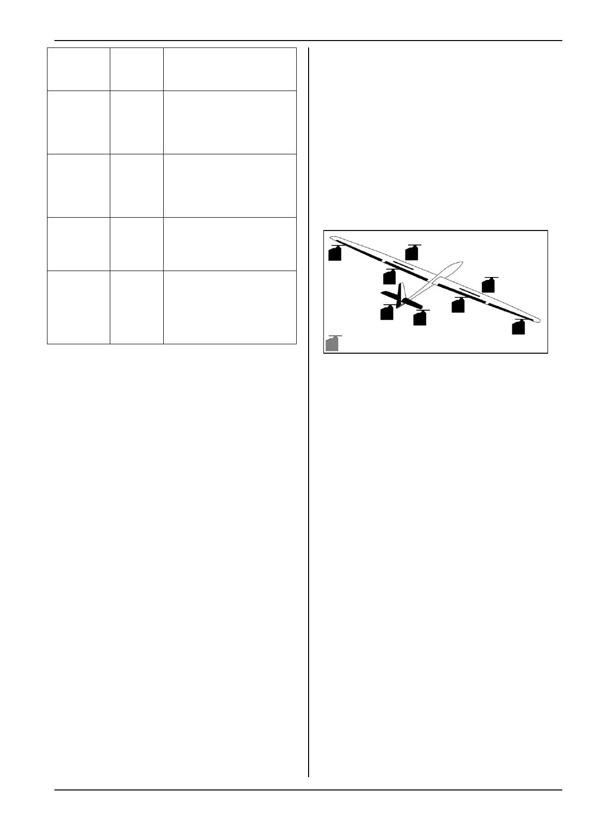
Assigned servos / receiver outputs:
1
2
4
5
6
3
7
8
9
Spoiler
Spoiler
AILERON+
Throttle
AILERON+
ELEVATR+
Rudder
FLAP+
FLAP+
Servo configuration MPX-UNI
Timer setting: Motor run time
Sum timer ´ controlled by Throttle (E).
Tow release instead of Throttle: ( 21.1.5.) GLIDER.
Fine-tuning:
!
Steps a. and b. ( 21.1.),
Check functions.
c. Activate throttle to elevator mixer
G, select ELEVATR+, select Thr -Tr input,
set 10% down-elevator.
If you wish to adjust the value in flight, allocate it to
one of the 3-D digi-adjusters ( 20.1.).
d. Special features when calibrating the servos
FLAP+ and AILERON+
(input: Spoiler, Parameter: offs = OFFSET)
Models with a four-flap wing generally employ what
is known as the Butterfly or Crow system as a land-
ing aid: ailerons max. up, camber-changing flaps
max. down. For this function the flap servos, in par-
ticular, have a highly asymmetrical working range:
The maximum control surface travel in the up-
direction (approx. 20°) is required for aileron con-
trol. For landing the flaps are required to deflect
down as far as possible in order to achieve maxi-
mum braking effect (if possible > 60°).
This means that the servo travel must be greatly
reduced in the up-direction, unless the servo output
lever is not already installed “offset” (mechanical
differential). As a result valuable servo travel is for-
feited, available servo power is wasted, and you
have to accept unnecessarily high gearbox play,
reduced servo resolution and increased shock
loads on servo gears in hard landings.