Manual
53
13.8. 13.8Throttle, and associated func-
tions
The illustration below shows how throttle limiter, throt-
tle curve and the collective pitch stick affect the throt-
tle function. The individual terms are explained in Sec-
tion ( 13.8.1.).
Since there are certain differences between electric
and I.C. (internal combustion) helicopters in this respect,
the instructions describe the settings for these two
power system types separately:
13.8.2. Throttle for electric helicopters
13.8.3. Throttle for I.C. helicopters
The illustration printed below shows the association
between all the settings and transmitter controls which
have a role to play in controlling the power system.
Points P1 to P5
define the shape of the throttle curve
Collective pitch stick controls throttle
Throttle limiter limits throttle upwards
Throttle min. limits throttle downwards.
P1
P2
P3
P4
P5
Throttle curve for helicopter
Throttle/speed controlle r
Programmable
throttle curve
Throttle limiter
Area blocked by
throttle limiter
Collective pitch stick
Actual
throttle course
Area blocked by
throttle min.
Throttle
min
Fig. 13.8.1.: General overview “Throttle for helicopters”
This graph contains the essential information for I.C.
powered model helicopters:
P1
P2
P3
P4
P5
Helicopter throttle
Throttle
Throttle curve
Idle
(Thr. min. + trim)
Thr. min .
Trim
range
(20%)
Throttle limiter
Fig. 13.8.2.: Overview for I.C. helicopters
Point P1 on the throttle curve is located at around
45%. From that point the throttle can be “pulled down”
to the value for Throttle Min. using the Limiter. How-
ever, the actual idle throttle setting is defined by the
sum of Throttle Min. and the set trim value. Starting
from Throttle Min., idle can be increased by up to
20%. This makes it possible to adjust the idle to suit
the current operating conditions.
13.8.1. What is the meaning of the terms Limiter,
Curve, Throttle Min., Trim, DTC and
Throttle cut?
Throttle limiter:
The throttle limiter restricts the maximum possible
throttle value. For normal flying the limiter should be
left at Maximum. All throttle values which are dictated
by the collective pitch stick in accordance with the set
throttle curve are also present at the Throttle channel.
Once the engine has been started, the throttle limiter
can be used slowly to raise the speed of the main ro-
tor “by hand”.
Throttle curve:
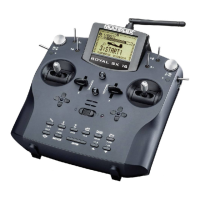
The throttle curve of the ROYAL SX has five points,
and determines how much throttle is assigned to the
various individual positions of the collective pitch stick.
The aim is a constant rotational speed, i.e. the higher
the collective pitch, the more the throttle is advanced.
Throttle Minimum and Throttle Trim (Idle):
Throttle Min. (minimum throttle) is used to set the en-
gine’s idle speed.
If you set the throttle limiter to minimum, the idle char-
acteristics of an I.C. engine can be fine-tuned using
the trim in order to suit the operating conditions (tem-
perature, humidity). Trimming is carried out by the trim
button adjacent to the stick which you have selected
(via stick Mode) to control Collective Pitch.
DTC:
DTC stands for Direct Throttle Control. If DTC is
switched on (CS/DTC switch in the ON position), the
throttle channel - regardless of whether it acts upon a
carburettor or a speed controller - is controlled directly
by the transmitter control assigned to Limiter (default
control is Slider F), and is independent of the position
of the collective pitch stick.
DTC is useful when you wish to start an I.C. engine,
or adjust the carburettor settings.
Throttle-cut:
If you hold this button pressed in, the throttle channel
is maintained in the position which you earlier se-
lected as Point P1 for the throttle servo under Servo
travel adjustment. This enables you to “switch off” an
I.C. engine, assuming that the carburettor barrel is
fully closed at this position ( Fig.13.8.2.).
The default choice for Throttle-cut is button H on the
right-hand side of the transmitter.
! Caution: in the case of electric helicopters you
must remember that the throttle channel jumps back
to the last used throttle value when you release the
Throttle-cut button. This could cause the main rotor to
start spinning again.
 Loading...
