Manual
87
19.4.2. Locking / unlocking flight phases
The flight phases are unlocked or locked using the
REV/CLR button. By locking a flight phase you can
avoid the danger of launching with a flight phase se-
lected which does not contain the correct settings.
If you operate a flight phase switch to select a locked
flight phase, you will hear a continuous beep to warn
you of your error. The last used flight phase remains
active, and its number is shown in Status displays 1, 2
and 3 ( 10.8.2.). The name of the locked flight
phase which you tried to access is shown crossed out.
How to lock / unlock flight phases:
First select a flight phase, and confirm your choice by
pressing the ENTER button or one of the 3-D digi-
adjusters.
The cursor now jumps to the flight phase name. At
this point you can toggle between “free” and “locked”
using the REV/CLR button.
Selecting a different name using the 3-D digi-adjuster
also unlocks a locked flight phase.
Note:
The active flight phase (marked with an x) cannot be
locked.
19.4.3. Copying flight phases
If you wish to start using different flight phases, we
recommend the following procedure:
First fly the model using just one flight phase, leaving
the other phases locked. Test-fly and adjust the model
until you are confident that it is trimmed perfectly. At
this stage the first flight phase should be copied. Now
when you switch to the new flight phase(s) you can be
sure that the model will continue to fly in the usual
way. All you have to do at this stage is carry out the
desired changes in the additional flight phases.
The active flight phase is marked with an x. The only
flight phase you can copy is the active one. The fol-
lowing steps are required:
a. Select the active phase ( x ) using the UP / DOWN
buttons (▲ / ▼), or alternatively using one of the
two 3-D digi-adjusters.
b. Press the 3-D digi-adjuster (or ENTER) twice,
the cursor jumps to the x.
c. Select the target phase to receive the copy, using
the UP / DOWN buttons (▲ / ▼) or alternatively
one of the two 3-D digi-adjusters. A letter c (= copy)
appears after the target phase name.
d. Press the ENTER button or one of the 3-D digi-
adjusters to conclude the copy process.
e. In the main menu ¦Memory activate the point
Flight phase:
¦Flight phase
¨Exit
1 HOVER
2 NORMAL x J>
3 THERMAL1 J>
4 START1 I>
Time OFF
19.4.4. Setting the flight phase transition time
In the bottom line of the menu you can set the tran-
sition time (Time) for moving between flight phases:
OFF 1sec 2sec 4sec
! Exception: auto-rotation
Switching into the AUTOROT flight phase always
occurs without any delay!
19.5. Checking / changing the Proper-
ties of the current model memory
Menu I Memory, Properties:
19.5.1. What is displayed?
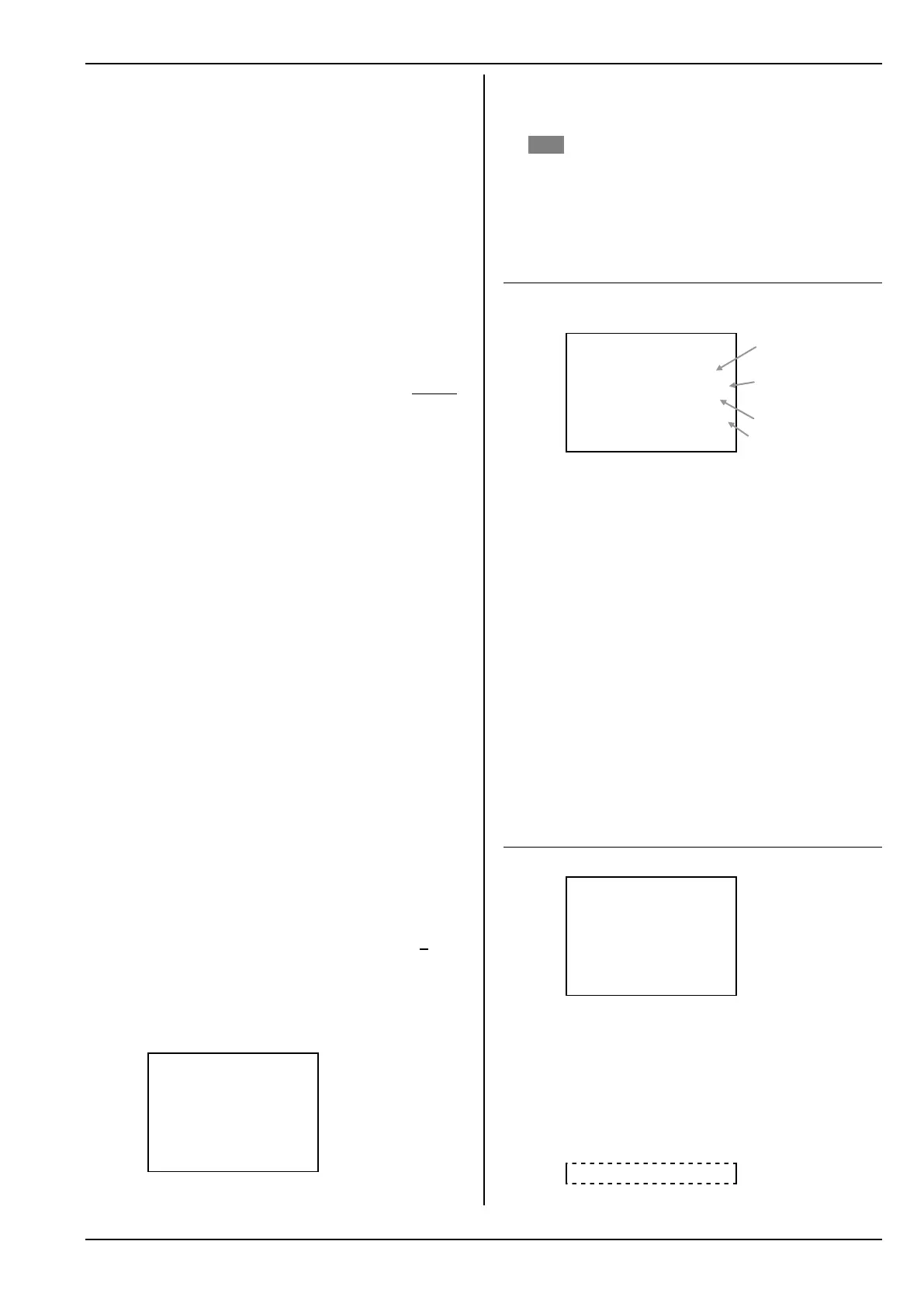
¦Properties
¨Exit
Template GLIDER
Mode 4: èé
Assignment GLIDER
Name Cularis
Template (cannot be changed!):
If you have used an “unsuitable” Template when
setting up a new model, you must erase the model
and create it anew.
19.5.2. What can be changed?
Stick Modes 1 to 4 are available:
The double arrows indicate the sticks which are
used to control elevator (è) and rudder (é)
( 14.3.).
Assignment:
When you set up a new model you select one list
from the five assignment lists. Your selection can
be changed subsequently in this menu
( 14.3.).
Model Name:
The model name can be entered using up to six-
teen characters
( 11.1.1.).
19.6. Setting up a New model
Menu: I Memory, New model:
¦New model
¨Exit
Memory nr. 3
Template GLIDER
Servo conf. MPX-UNI
Mode 4: è é
Assignment GLIDER
OK
a. Memory nr.
For a new model the software uses the transmit-
ter's first available vacant memory. It is not pos-
sible to choose the memory.
If you wish to store the new model in a different
memory, you can subsequently copy the new
model into a different memory location ( 19.2.).
If all the memories are occupied, the screen shows:
Memory nr. -1
Template used to create
the model
Selected stick mode
(elevator / rudder right)
Selected assignment
Model name
a.
b.
c.
d.
e.
f.