Manual
23
the Throttle CUT switch has not been operated.
As long as the on-screen warning is visible, …
the servo assigned to throttle (or the speed control-
ler) remains in the Idle position (or motor OFF),
and
all other control functions can still be operated
normally.
The throttle lock is terminated when …
the throttle control is moved to the Idle position (or
motor OFF),
or
the Throttle CUT control is operated (default button H)
or
you press the REV/CLR button.
! Caution! The motor might start to run!
If you override the throttle lock using the REV/CLR
button or Throttle CUT, the throttle channel will jump
to the value defined by the assigned throttle control.
10.4.2. Throttle-check for model helicopters
Helicopter throttle is affected by the following trans-
mitter controls:
a. Throttle CUT switch (default: button H).
b. Direct Throttle switch
(DTC = Direct Throttle Control, default: switch N).
c. Collective pitch stick via the throttle curve.
d. Throttle limiter (default: slider F).
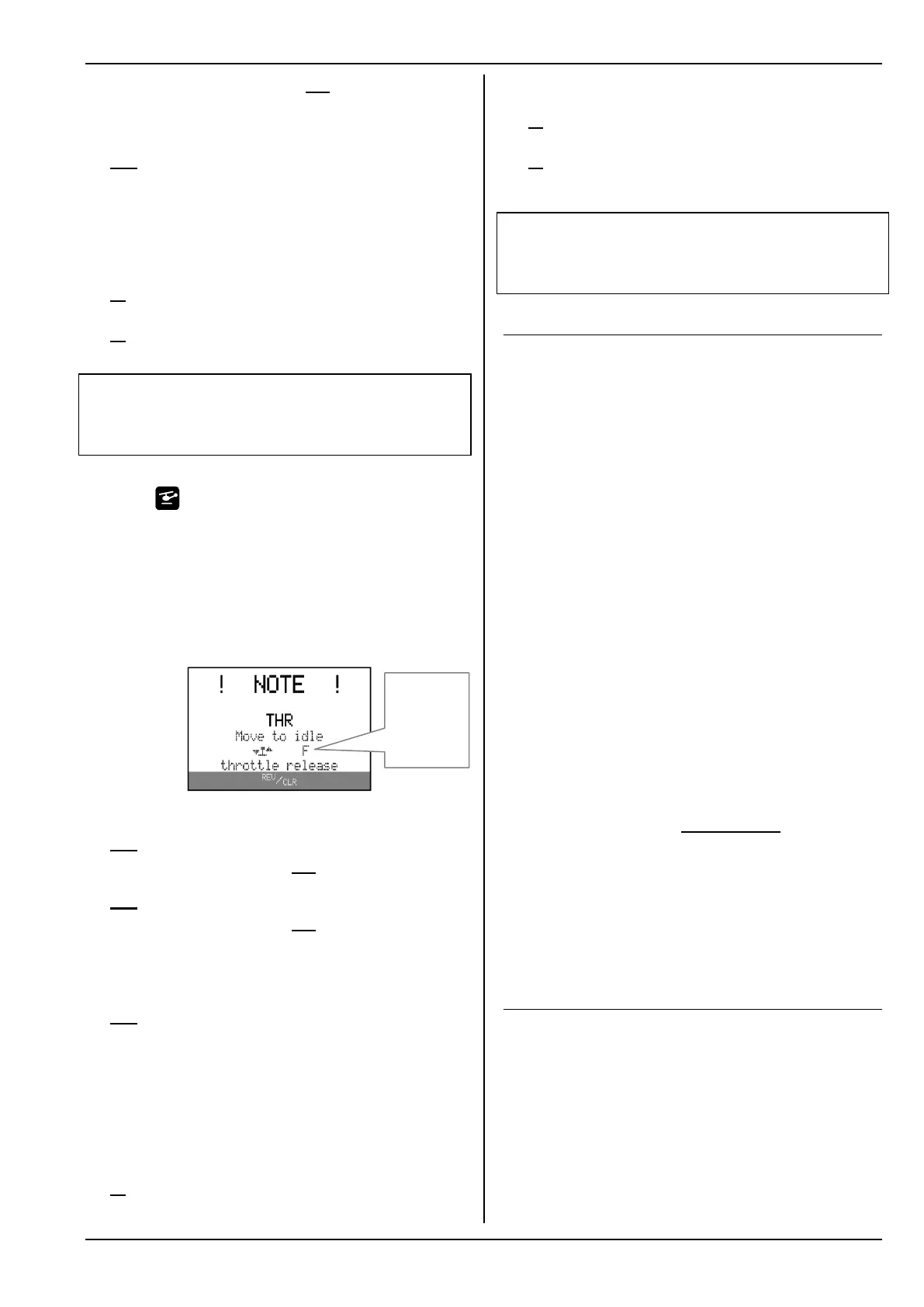
This warning appears on-screen if:
Throttle-Check (Check Thr.) is set to ON ( 10.4.)
and
the collective pitch stick is not at the Idle position
(collective pitch minimum)
and
the Throttle CUT switch is not active.
As long as the note is visible on the screen, …
the servo assigned to throttle (or the speed control-
ler) remains in the Idle position (or motor OFF)
and
all other control functions can still be operated
normally.
The throttle lock is terminated when …
the collective pitch stick is moved to the Collective
Pitch Minimum position (provided that: point P1
on the throttle curve is lower than or equal to the
set value for Throttle Minimum Min.)
or
EMERGENCY throttle OFF is operated (default:
button H)
or
the throttle limiter is moved to the Minimum position
or
you press the REV/CLR button.
! Caution! The motor might start to run!
If you override the throttle lock using the REV/CLR
button or Throttle CUT, the throttle will jump to the
value defined by the assigned throttle control.
10.5. Binding Procedure
The transmitter and receiver must be “introduced” to
each other once; this process is known as “binding”.
! Note:
You will find general information on the subject of
binding, and on fault-finding and correction relating to
the binding procedure, in the operating instructions
supplied with your MULTIPLEX M-LINK receiver.
The binding procedure in detail:
1. Place the transmitter and the receiver aerial(s) im-
mediately adjacent to each other.
2. Switch the ROYALevo, ROYAL SX or ROYAL SX
M-LINK transmitter ON in binding mode:
Hold button L on the transmitter pressed in.
Switch the transmitter ON.
Release button L:
The red LED on the transmitter flashes rap-
idly, and the message “BINDING!” flashes
on the transmitter screen in all status dis-
plays with the exception of status display 4.
3. Switch the M-LINK receiver ON in binding mode
(see the
M-LINK receiver operating instructions):
The binding process is now in progress.
4. Once the transmitter and receiver have detected
each other, both units automatically switch over
to regular transmit / receive mode (Normal opera-
tions 11.):
The red LED on the transmitter flashes ap-
proximately every two seconds, and the flash-
ing message “BINDING!” disappears.
! Note: the binding process usually only takes a few
seconds
10.6. Range Checking
Regular range checks are very important - even when
using a 2.4 GHz system - in order to ensure reliable
operation of the radio control system, and to give you
a chance to detect sources of interference in good
time. This applies in particular:
Before the use of new or changed components, or
existing components in a new or modified arrange-
ment.
Before re-using radio control system components
which were previously involved in a crash or a hard
landing.
Indicator for
the throttle
and throttle
limiter con-
trols