Manual
39
12.7. Adjusting elevator, activating ele-
vator mixers
(Mixer ELEVATR+)
In the template 4 FLAPS the elevator servo is already
assigned to the mixer ELEVATR+. Various mixers are
added to the signal in order to compensate for un-
wanted trim changes (e.g. from Spoiler or Throttle).
This is how the mixer is defined:
¡Define mixer
¨Exit
Name ELEVATR+
1 Elevator ON š
2 Spoiler ON œ
3 Flap ON š
4 Thr -Tr ON ›-
5 -------- --- ---
12.7.1. Spoiler to elevator = Spoiler compen-
sation
(Spoiler input to ELEVATR+ mixer)
When the spoilers are extended (or when Butterfly is
activated), many models require elevator trim correc-
tion.
The default method of working of the Spoiler input in
the elevator mixer is single-sided with two curve
points (œ). Point 2 (pt2) defines the elevator deflection
at full extension of Spoiler / Butterfly (57%). Point 1
(pt1) is generally set to half of Point 2 (pt1 = 28%) to
ensure that response to the control is linear.
If the effect of the spoilers themselves is non-linear,
then non-linear travel can be set to compensate for
this. For instance, Point 1 (pt1) could be set to ⅓ or
¼ of Point 2 (pt2) to obtain this effect:
£5x Mixer.ELEVATR+
¨Exit
œ pt1 pt2
Elevator– 100% 100% *
Spoiler – 28% 57% *
Flap – OFF OFF *
Thr -Tr – OFF OFF *
--------–-----------
12.7.2. Throttle to elevator = Throttle compen-
sation
(Thr -Tr input to ELEVATR+ mixer)
Many models tend to “balloon up” when the throttle is
opened (incorrect downthrust setting); this can be cor-
rected using down-elevator (stick forward).
The default method of working of the Throttle input in
the elevator mixer is single-sided with deadband (›-).
If down-elevator correction is only required after, say,
about the 1/3 throttle point, set 33% as deadband:
£5x Mixer.ELEVATR+
¨Exit
œ- dead trv
Elevator– 100% 100% *
Spoiler – 20% 57% *
Flap – OFF OFF *
Thr -Tr – 33% OFF *
-------- ---- ----
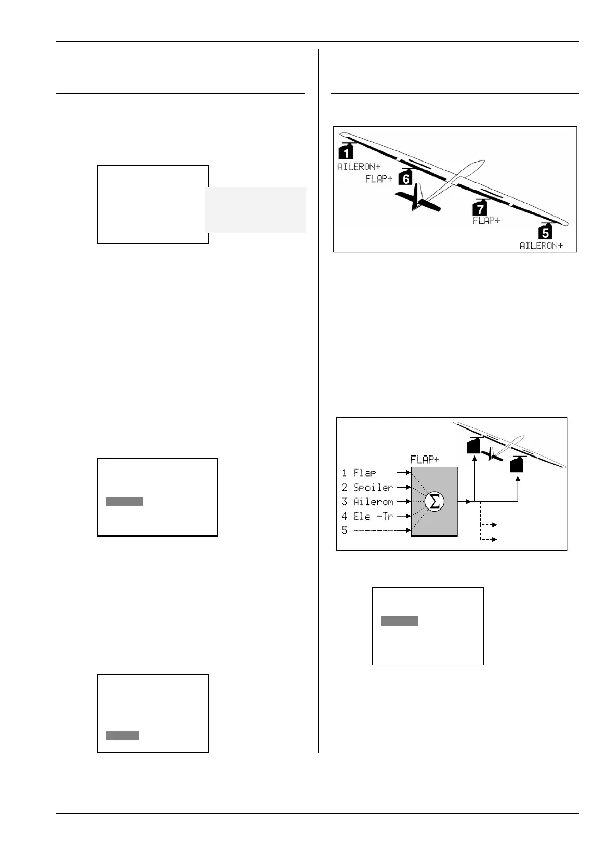
12.8. Activating inboard flaps (camber-
changing flaps)
(Mixer FLAP+)
In the template 4 FLAPS servos 6 and 7 are assigned
to the FLAP+ mixer (camber-changing flap):
Fig. 12.8.1.: Four-flap wing
This mixer can be used to implement the following
functions:
Butterfly (Crow)
as glide path control or landing aid
Camber-changing flaps
for modifying the wing airfoil (thermal, speed)
Aileron support for better manoeuvrability
Snap-Flap (elevator to flap)
e.g. for aerobatics.
The structure of the FLAP+ mixer:
6
7
Mixer
input
Nr. Name
Mixer
name
Further servos
if required
Fig. 12.8.2.: The FLAP+ mixer in principle
These are the default settings for the FLAP+ mixer:
£5x Mixer.FLAP+
¨Exit
š trv' trv#
Flap – OFF OFF *
Spoiler – OFF 100% *
Aileron – OFF OFF *
Ele -–Tr– OFF OFF --
--------– ---------
In this mixer the Spoiler input is assigned a default
value of 100% travel (for Butterfly). All the other inputs
are OFF.
How the inputs work:
asymmetrical
single-sided, two curve points
asymmetrical
single-sided, with deadband