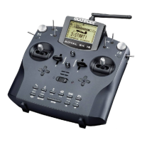
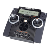
ROYAL SX
86
19.3. Erasing model memories
Move to the main menu ¦Memory and activate the
point Erase.
In this menu the first step is to select the model mem-
ory which is to be erased.
A list of all model memories is now displayed:
¦Erase
¨Exit
1 EasyStar
2 Twister x
3 Gemini
4 ---------
5 Cularis
ª6 FunJet red
Use the 3-D digi-adjuster or the ▲ / ▼ buttons to se-
lect the model which you wish to erase.
Note: you cannot erase the current model
The current model (marked with x) cannot be erased.
If you wish to erase the current model, you must first
select any other model ( 19.1.).
Now press the 3-D digi-adjuster or the ENTER button
in order to initiate the erasure process.
The screen now displays a request to confirm the erasure;
this is intended to prevent you accidentally erasing a
model:
Erase selected
model?
Yes->
No->ENTER
Pressing the REV/CLR button erases the model,
whereas pressing ENTER interrupts the process,
leaving the model data in the memory unchanged.
19.4. Managing Flight phases
Flight phases are simply settings / data sets for a
model which can be called up by operating a switch.
The data sets are optimised for particular flight tasks.
Flight phases enable you to adjust the transmitter con-
trol settings to suit the requirements of the task in
hand, e.g. reduced control travels for SPEED flying,
lowered flaps for LANDING, different collective pitch
and throttle curves for model helicopters, etc.; all this
can be carried out separately for each flight phase. All
the settings which may be changed between flight
phases are marked with the flight phase code number
1 … 4 in the transmitter control menus ( 14.). The
ROYAL SX also features digital trims which are flight
phase specific, i.e. the trims can be set differently and
stored for each flight phase. This simply means that it
is possible to trim the model perfectly for each flight
phase.
The ROYAL SX allows you to set up four flight phases.
However, by default the assignment lists contain no
assigned flight phase select switches.
It is possible to set up a “soft” transition (1, 2 or 4sec
(seconds)) when switching from one flight phase to
another; this avoids abrupt changes in servo position
when you select the next phase.
If you set the Time parameter to OFF , the change-
over occurs immediately.
Note:
The helicopter flight phase “Auto-rotation” is the
exception to this rule. When you operate the
AUTOROT switch, the software immediately switches
to the AUTOROT flight phase.
The Flight Phase menu may look like this for a
fixed-wing model (Fig. 19.4.1.) or a helicopter (Fig.
19.4.2):
Fig. 19.4.1.: Fig: 19.4.2.:
Flight phases, fixed-w. Flight phases, helicopter
Fig. 19.4.1. shows the following information:
a. The first column shows the number of the flight
phase, followed by its name.
b. Flight phases 1 and 3 and 4 are locked
(names crossed-through).
c. Flight phase 2 NORMAL is active
(x after the name).
d. The flight phase switch is J> on the right-hand
side.
e. Time shows the flight phase transition time.
The same applies to the four helicopter flight phases
which are shown in Fig. 19.4.2.
19.4.1. Selecting flight phase names
You can assign to each flight phase any of the thirteen
names included in the list below:
NORMAL, START1, START2, THERMAL1, THERMAL2,
SPEED1, SPEED2, CRUISE, LANDING, AUTOROT,
HOVER, 3D, ACRO
The sole purpose of the flight phase name is to pro-
vide additional information. In terms of the properties
of the phase it is the number of the phase which is
crucial, ie. flight phases of the same name do not
necessarily have the same settings or properties.
Changing a flight phase name:
Use the ▲ / ▼ buttons (or alternatively one of the two
3-D digi-adjusters) to select a flight phase, and con-
firm your choice by pressing the ENTER button or one
of the 3-D digi-adjusters.
The cursor jumps to the name input field.
You can now select a suitable name using the ▲ / ▼
buttons or one of the two 3-D digi-adjusters.
Pressing the ENTER button or pressing one of the 3-D
digi-adjusters once concludes the input process.
Note: changing the name of the active flight phase
When you have selected the active flight phase
(marked with the letter “x”), you must press the 3-D
digi-adjuster or ENTER twice in order to conclude the
procedure.
Current model memory
Model memory selected
for erasure
 Loading...
