PAGE 40 — LD6 RIDE-ON POWER TROWEL • OPERATION MANUAL — REV. #0 (02/10/20)
BLADE REPLACEMENT
It is recommended to replace all of the trowel blades at the
same time. If only one or some of the blades are changed,
the machine may wobble or bounce and will not finish
concrete consistently.
1. Place the trowel on a flat, level surface, with blocks
under the main guard ring for support.
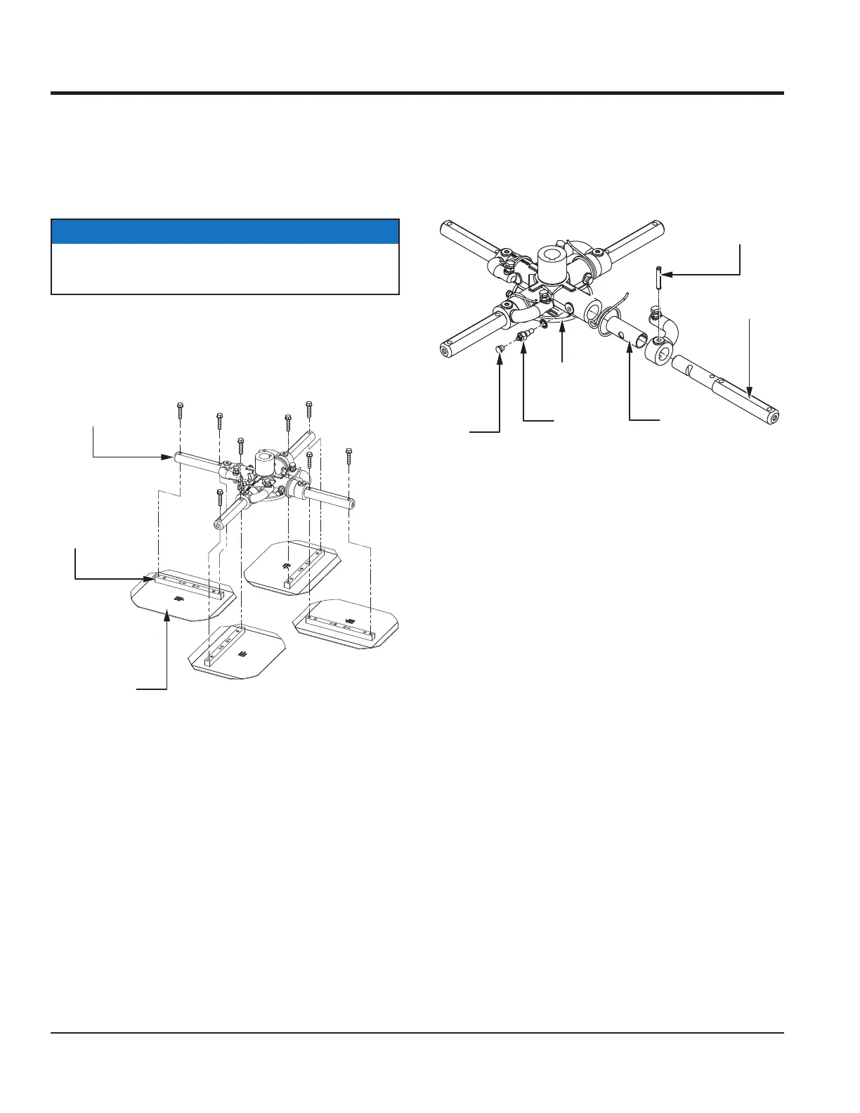
2. Remove the bolts from each of the trowel arms, then
remove the blades as shown in Figure 45.
Figure 45. Blade Removal
3. Wire brush and remove all concrete and debris from
each of the four trowel arms. This is important to
properly seat the new blades.
4. Install the new blades, maintaining the proper blade
orientation as noted during removal. Secure with the
bolts that were removed earlier.
NOTICE
Please note the orientation of each blade on the trowel
arm before removal.
TROWEL ARM
TROWEL
BLADE
BLADE
ATTACHMENT
BAR
TROWEL ARM REMOVAL
1. Each trowel arm is held in place at the spider plate
by a Zerk grease fitting (hex head bolt). Remove the
Zerk grease fitting and the roll pin from the spider plate
(Figure 46).
Figure 46. Trowel Arm Removal
2. Remove the trowel arm from the spider plate
(Figure 46).
3. Carefully remove the trowel arm bushing (Figure 46).
4. Examine the trowel arm bushing, and clean it
if necessary. Replace the bushing if it is worn
or out-of-round.
TROWEL
ARM
ROLL PIN
SPIDER PLATE
ZERK
GREASE
CAP
BUSHING
MAINTENANCE