LD6 RIDE-ON POWER TROWEL • OPERATION MANUAL — REV. #0 (02/10/20) — PAGE 39
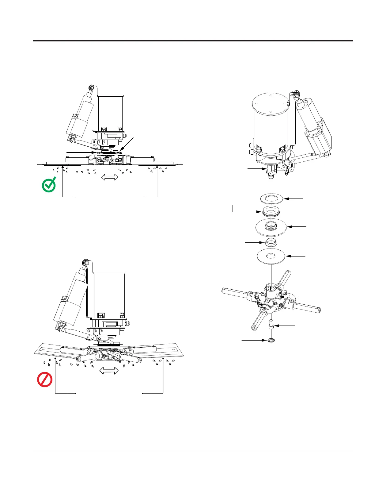
2. Pitch the blades as flat as possible. The adjustment
bolts should all barely make contact with the lower wear
plate on the spider. Figure 42 illustrates the correct
alignment for a spider plate as shipped from the factory.
Figure 42. Correct Spider Plate Alignment
3. If any adjustment bolts are not making contact with
the lower wear plate, adjustment will be necessary.
Figure 43 illustrates incorrect alignment, worn spider
bushings, or bent trowel arms.
Figure 43. Incorrect Spider Plate Alignment
SURFACE
ADJUSTMENT
BOLTS
LOWER WEAR
PLATE
FLAT FLAT
CORRECT ALIGNMENT
NO
SURFACE
DISHED EFFECT ON
FINISHED CONCRETE
SPIDER REMOVAL
1. Remove and set aside the cap plug and retaining screw
securing the spider assembly to the hydraulic motor
shaft (Figure 44).
Figure 44. Spider Removal
2. Carefully lift the upper trowel assembly off of the spider
assembly. A slight tap with a rubber mallet may be
necessary to dislodge the spider from the hydraulic
motor shaft.
UPPER WEAR
PLATE
THRUST
COLLAR BEARING
THRUST
COLLAR
THRUST
COLLAR BUSHING
LOWER WEAR
PLATE
SPIDER PLATE
SOCKET HEAD
SCREW
PLUG
HYDRAULIC
MOTOR SHAFT
MAINTENANCE