Setup and connection
5.2 Setup with foundation
CAUTION
Material damage due to base plate distortion!
Set and fasten the base plate on the foundati on as
described in the following.
5.2.1 Setting the pump aggregate on the foundation
✔ Implements, tools and materials:
– foundation bolts (→ Setup drawing)
– steel washers
– mortar grout, non-shrinking
– spirit level
1. Lift the pump aggregate (→ 4.1 Transport, Page 13).
2. Working from below, hang the foundation bolts in the fixa-
tion holes of the base plate.
Observe the manufacturer's instruction when using chem-
ical anchors.
3. Set down the pump aggregate on the foundation. When
doing this, sink the foundation bolts into the prepared
anchoring holes.
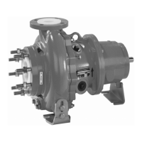
32 1 2
Fig. 9 Setup with foundation
4. Use steel washers to align the pump aggregate to height
and system measures as described in the following:
– Position 1 steel washer (2) each lef t and right of each
foundation bolt (1).
– If the distance between anchoring holes is > 750 m m,
position additional steel washer (3) centrally at each
side of the base plate.
5. Make certain that the base plate and the steel washers are
in full surface contact.
6. Use machine spirit level to check that the allowable height
deviation (1 mm/m) lengthwise and crosswise is not
exceeded.
7. Repeat procedure until the base plate is correctly aligned.
5.2.2 Fastening the pump aggregate
Filling out the base plate with mortar grout will improve the
damping behavior.
1. Fill the anchoring holes with mortar grout.
2. Once the mortar grout has set, screw on the base
plate at three points with the specified tightening torque
(→ 9.2.4 Tightening torques, Page 41).
3. Before tightening the remaining bolts, compensate any
unevenness of the fixation surface, using metal shims n ext
to each bolt.
4. To inspect the pump aggregate for distortions, using a hair
ruler:
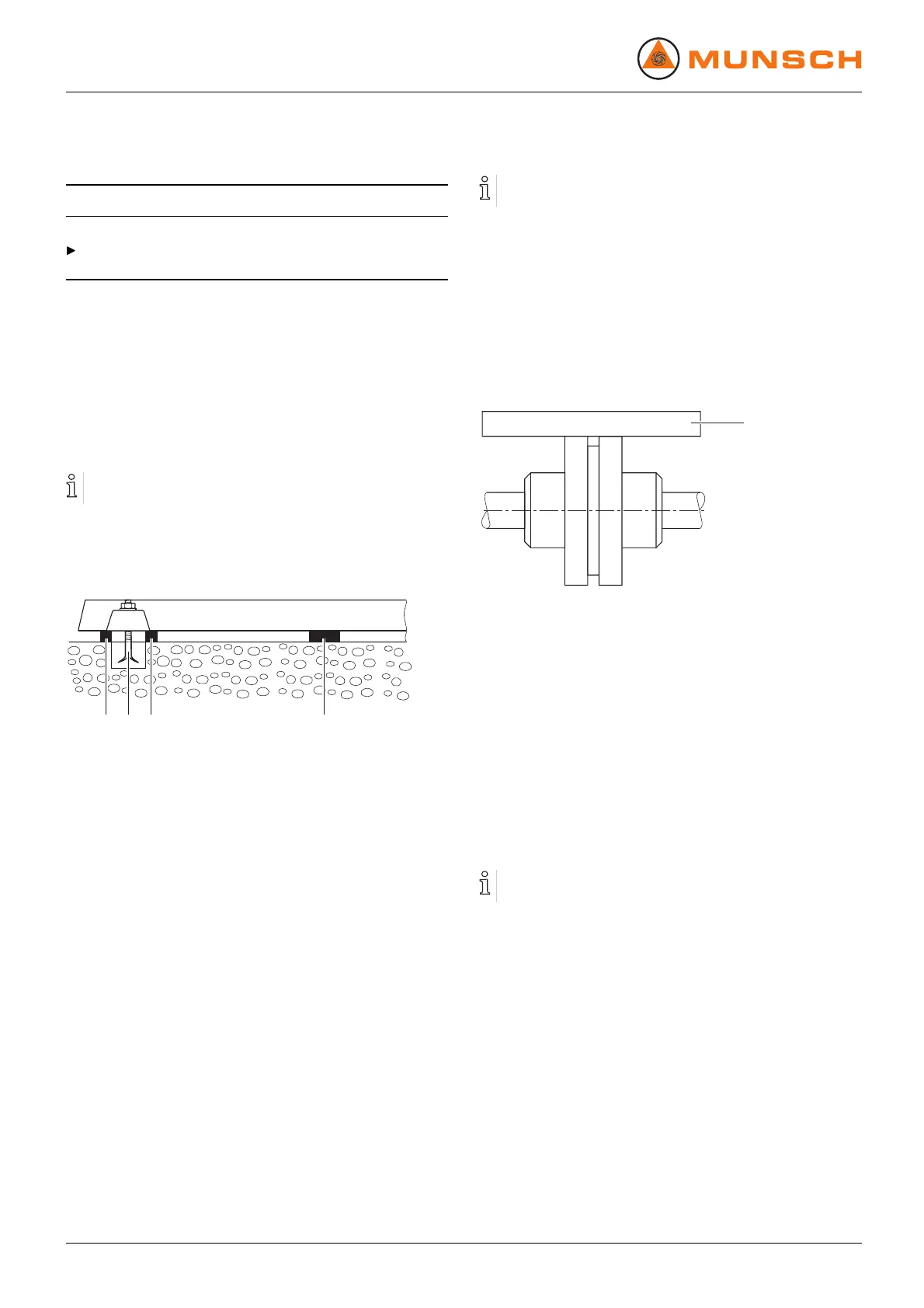
1
Fig. 10 Checking for distortions
– Measure in two planes at an angle of 90° to each other
on the circumference of the coupling.
– Measure the light gap at the outer diameter with hair
ruler (1):
Position the hair ruler across both halves of the cou-
pling.
If there are major deviations, loosen the fixation at the
base plate and correct the distortion by inserting more
shims.
– Fill the base plate with molding material if applicable.
Knock on the base plate to ensure that no cavities are
created in the process.
Couplings with a spacer piece (Dismountable coupling ) can
also be inspected with a dial gauge.
16 NPC series BA-2005.07 EN – 02