Maintenance
7.4 Assembling
7.4.1 Preparations for assembling
1. For assembling take note of the following:
– Replace worn components with authentic replacement
parts.
– Replace gaskets, insert new gaskets so that they can-
not rotate.
– Observe specified tightening torque (→ 9.2.4 Tighten-
ing torques, Page 41).
– Refit components concentrically without canting
according to the prepared orientation and position
markings.
2. Clean all components (→ 9.2.6 Detergents, Page 42). Do
not remove the prepared marki ngs.
3. Assemble the pump (→ Sectional drawing).
Assembly is carried out in reverse order of disassembly.
The following sections only describe particular aspects to
be observed when assembling the product.
7.4.2 Fitting the pump shaft
With roller bearings without lifetime lubrication
1. Heat up inner ball race of radial roller bearing 322 and press
it onto pump shaft 211.
2. Heat up radial ball bearing 321 and press it onto pump shaft
211.
3. Cool down radial ball bearing 321 and grease it if it is
grease-lubricated.
4. Screw bearing nut 923 onto pump shaft 211.
5. Screw in threaded pins with 1 drop of LOCTITE 243 in bear-
ing nut 923 and apply color markings to the threaded pins.
6. Insert circlip 932.1 in bearing bracket 330.
7. Press in radial roller bearing 322 and grease it if it is grease-
lubricated.
8. Insert circlip 932.1.
9. Press pump shaft 211 into bearing bracket 330.
10. For bearing bracket L18B (→ Figure Bearing bracket L18B
(grease-lubricated bearing), Page 39).
With lifetime-lubricated roller bearings
1. Heat up radial ball bearings 321 and 321.6 and press them
onto pump shaft 211.
2. Screw bearing nut 923 onto pump shaft 211.
3. Screw in threaded pins with 1 drop of LOCTITE 243 in bear-
ing nut 923 and apply color markings to the threaded pins.
4. Insert circlip 932.1 in bearing bracket 330.
5. Press pump shaft 211 into bearing bracket 330.
7.4.3 Fitting the bearing bracket
1. Insert radial shaft seal ring 421.2 and O-ring 412.12 into
bearing cover 360.
2. Screw on bearing cover 360 with socket head cap screw
914.3.
3. Insert radial shaft seal ring 421.1 in bearing bracket 330.
4. Screw on bearing cover 360.4 with socket head cap scre ws
937.
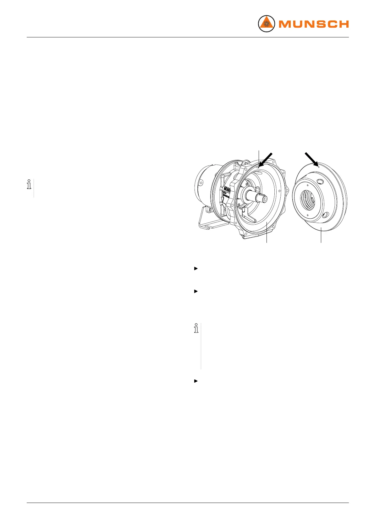
7.4.4 Fitting the casing cover
560
146 161
Fig. 25 Fitting the casing cover
Fit casing cover 161 into intermediate lantern 146.
7.4.5 Fitting the pump into the installation
(→ 5 Setup and connection, Page 15).
7.5 Ordering replacement parts
For trouble-free replacement in case of any fault we rec-
ommend keeping a complete slide-in units or replacement
pumps available on site.
The application guidelines according to DIN 24296 rec-
ommend provisioning for tw o years of continuous use
(→ 9.3 Replacement parts for 2 years of continuous oper-
ation according to DIN 24296, Page 43).
Have the following information ready to hand for ordering
replacement parts (→ Type plate):
– short designation of the pump
– serial number
– construction year
– part number
– designation
– quantity
30 NPC series BA-2005.07 EN – 02