Setup and connection
5.3 Setup without foundation
✔ Implements, tools and materials:
–Wrench
– Spirit level
1
1
1
1
2
3
4
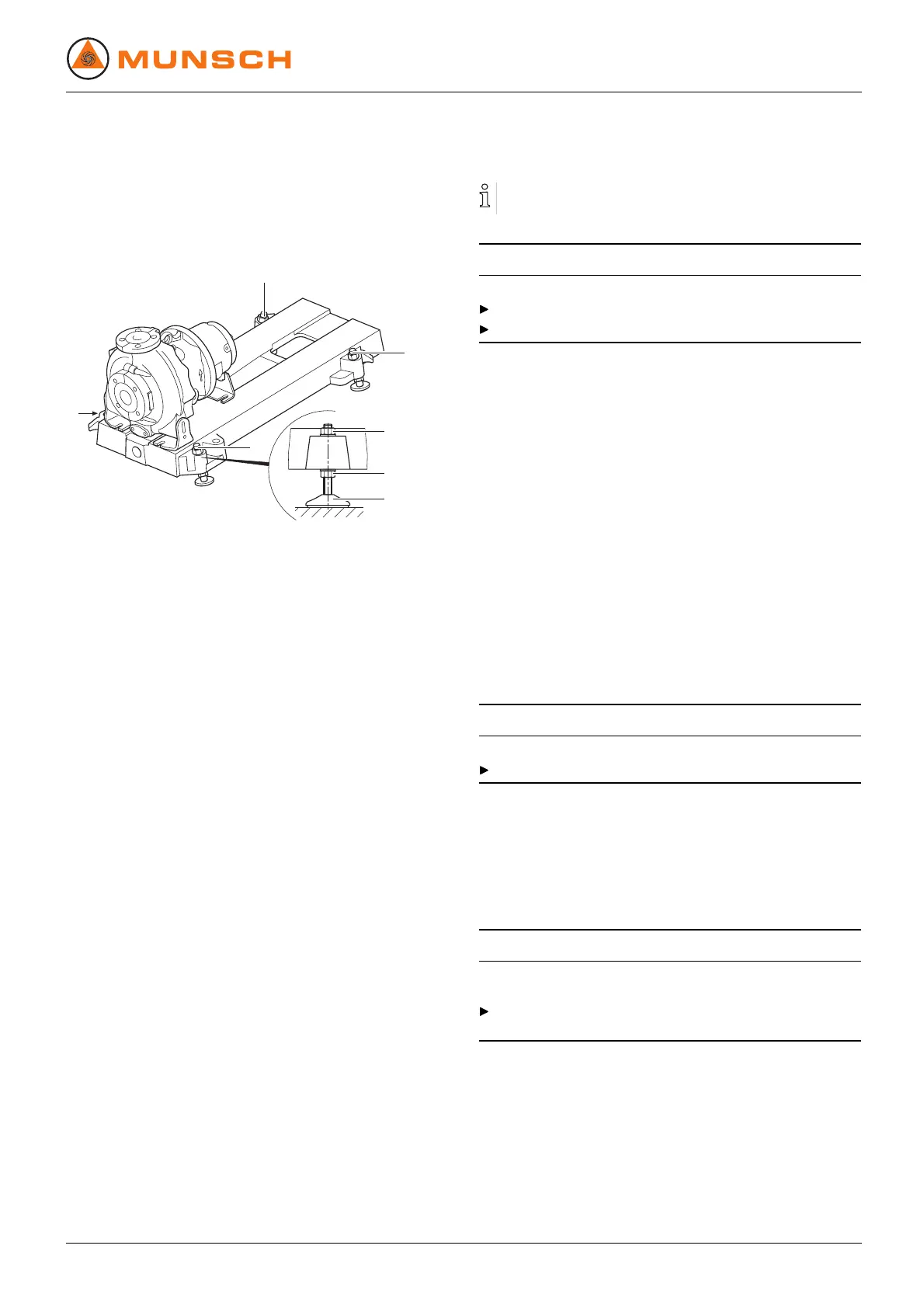
Fig. 11 Setup without foundation
1. Lift the pump aggregate (→ 4.1.2 Lifting, Page 13).
2. Mount the four leveling feet (1) as shown in the figure.
3. Set down the pump aggregate on the setup surface.
4. Adjust the height of the base plate using leveling feet (1)
as shown above:
– Use wrench to hold the hexagon at leveling foot (4).
– Slacken hexagon nut (2).
– Adjust height by turning hexagon nut (3).
– Tighten hexagon nut (2) (→ 9.2.4 Tightening torques,
Page 41).
– Use machine spirit level to check that the allowable
height deviation (1 mm/m) lengthwise and crosswise
is not exceeded.
– Repeat procedure until the base plate is aligned cor-
rectly.
5.4 Mounting the motor
Only necessary if the pump aggregate is assembled at he
setup site.
CAUTION
Material damage caused by knocks and blo ws!
Do not cant the coupling halve s when pushing on the motor.
Do not knock or hit any component of the pump.
1. Apply a very thin film of molybdenum sulfite (e.g. Molykote)
on the pump and motor shaft en ds.
2. Insert keys.
3. Without a mounting device: Remove rubber buffers and
heat coupling halves to approx. 100 °C.
4. Slide on the pump-side and motor-side coupling halves
until the shaft end and the coupling center are flush with
each other. Keep to the specified distance between the
coupling halves (→ Assembly i nstructions for the coupling).
5. Tighten the threaded pins at both coupling halves.
6. Use suitable metal shims at the motor to adjust the motor
shaft end to the height of the pump shaft end.
7. Turn in the motor screws, but do not tighten them yet
(→ 5.9 Aligning the motor, Page 20).
5.5 Planning the piping
5.5.1 Avoid contamination of the piping
CAUTION
Material damage due to impurities in the pump!
Make certain that no impurities can get into the pump.
1. Clean all piping components and armatures prior to assem-
bly.
2. Ensure that no flange gaskets are protruding inwards.
3. Remove blind flanges, plugs, protective foils and/or protec-
tive paints on flanges.
5.5.2 Specifying supports and flange connections
CAUTION
Material damage due to excessive forces and torque from
piping on the pump!
Do not exceed allowable limits (→ 9.2.7 Socket loads
according to ISO 5199, Page 42).
1. Calculate pipe forces and take into account every possible
operating condition:
– cold/warm
– empty/full
– unpressurized/pressurized
– position shifts of flanges
2. Ensure that pipe supports have permanent low-friction
properties and will not seize up through corrosion.
EN – 02 BA-2005.07 NPC series 17