Setup and connection
5.5.3 Specifying nominal widths
Keep flow resistance in pipes as low as possible.
1. Specify suction pipe nominal width ≥ suction flange nominal
width.
2. Specify pressure pipe nominal width ≥ pressure flange
nominal width.
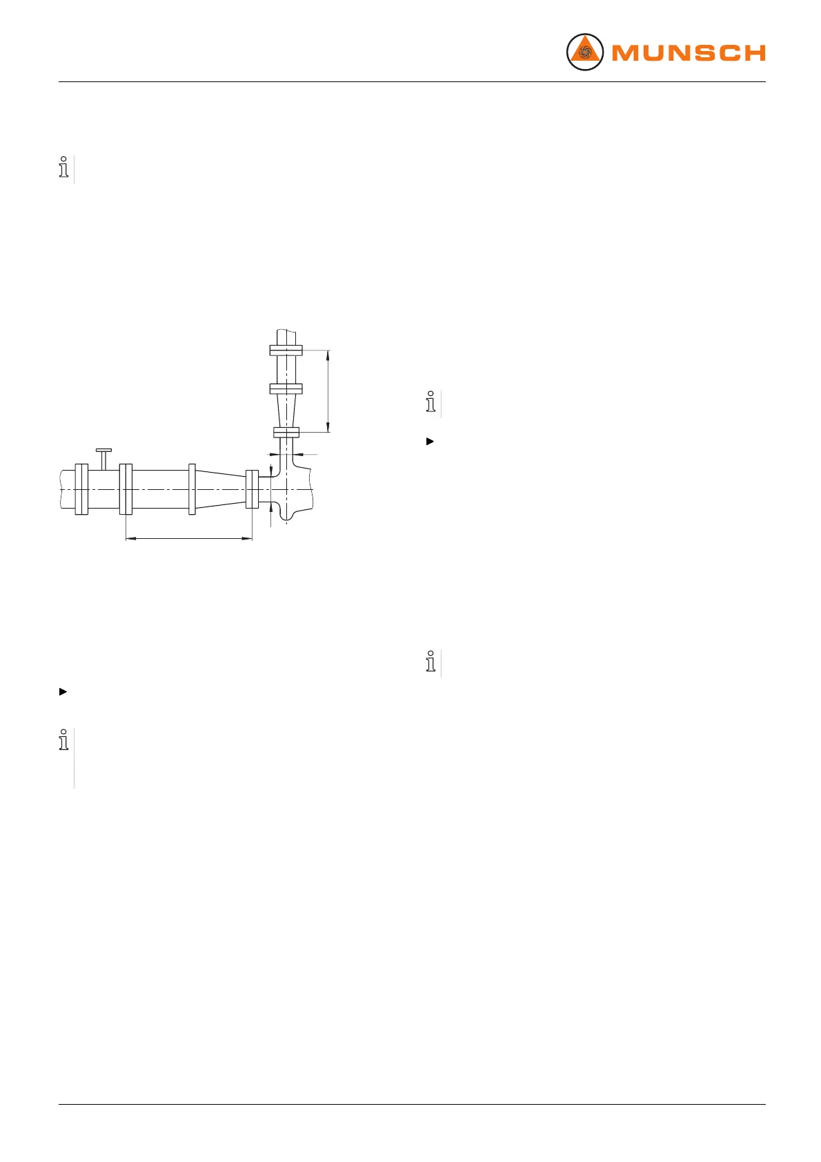
5.5.4 Specifying pipe lengths
C
D
B
A
Fig. 12 Straight pipe lengths upstream and downstream
of the pump (recommended)
A>5xDNs
B DNs
C DNd
D>5xDNd
Observe recommended m inimum parameters when install-
ing the pump.
Suction side: Shorter pipes are allowable but can restrict
hydraulic performance data.
Pressure side: Shorter pipes are allowable but can lead to
increased operating noise.
5.5.5 Optimizing cross-section and direction changes
1. Avoid radii of curvature smaller than 1.5 times the nominal
pipe width.
2. Avoid abrupt changes of cross-section along the piping
system.
5.5.6 Arranging for safety and control devices
(recommended)
Avoiding contamination
1. Integrate filter into the suction pipe.
2. To monitor contamination, m ount a differential pressure
gage with a contact manometer.
Avoiding rev erse running
1. Install a check valve between the pressure socket and the
gate valve to ensure that the medium will not flow back
whenthepumpisswitchedoff.
2. To allow bleeding, provide a bleeding connection between
the pressure socket and the check valve.
Providing for isolating and shut-off devices for the pipes
For maintenance and r epair work.
Provide for shut-off devices in the suction and pressure
pipes.
Allowing the measurement of the operating conditions
1. Provide for manometers for p ressure measurements in
suction and pressure pipes.
2. Provide for motor-side torque measurement.
3. Provide for pump-side temperature measurement.
5.6 Connecting the pipes
5.6.1 Installing auxiliary pipes
Follow manufacturers' specifications of any existing auxil-
iary operating system.
1. Install auxiliary piping to auxiliary unions, ensuring stress-
free and sealed connections (→ Setup drawing).
2. To avoid air enclosures: run pipes with a continuous slope
up to the pump.
5.6.2 Installing the suction pipe
1. Remove transport and sealing covers at the pump.
2. To avoid air enclosures: run pipes with a continuous slope
up to the pump.
3. Ensure that no gaskets are protruding inwards.
4. For suction ope ration: Install a foot valve in t he suction line
to prevent the pump an d suction pipe from running em pty
during downtime.
5.6.3 Installing the pressure pipe
1. Remove transport and sealing covers at the pump.
2. Mount the pressure pipe.
3. Ensure that no gaskets are protruding inwards.
18 NPC series BA-2005.07 EN – 02