Setup and connection
5.8 Fine alignment of the coupling
DANGER
Risk of death due to rotating parts!
Isolate the motor from its supply voltage and keep it locked
in that state while carrying out any fitting or maintenance
work.
CAUTION
Material damage due to incorrect alignment of the cou-
pling!
If there is any height, lateral or angle misalignment, align
the motor exactly w ith the pump.
For detailed information and special couplings: (→ Manu-
facturers instructions).
Inspecting the coupling alignment
✔ Implements, tools and materials:
– feeler gage
– hair ruler
– dial gage (can be used for coupling with a spacer piece)
– other suitable tools, e.g. laser alignment instrument
1
2
A
Fig. 13 Inspecting the coupling alignment
1. Measure in two planes at an angle of 90° to each other on
the circumference of the coupling.
2. Measure the light gap to the outer diameter with hair ruler
(1):
– Position the hair ruler across both halves of the cou-
pling.
– If there is a light gap at the outer diameter, align the
motor (→ 5.9 Aligning the motor, Page 20).
3. Measure the gap using feeler gage (2):
– Allowable gap (→ Setup drawing).
– Use the feeler gage for measuring gap width (A)
between the coupling halves.
– If the gap width is outside the allowable range, align
the motor (→ 5.9 Aligning the motor, Page 20).
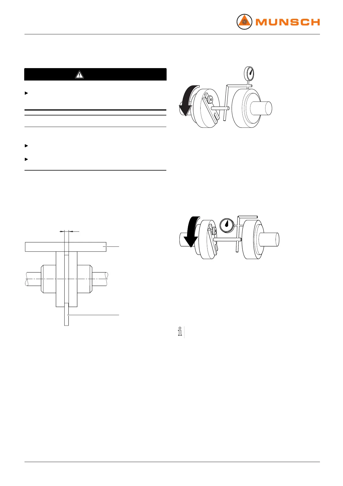
Fig. 14 Inspecting for lateral and height misalignment
4. Inspect for lateral and height misalignments using the dial
gage:
– Carry out the measurement as shown in the figure.
– If there is any lateral or height misalignment, align the
motor (→ 5.9 Aligning the motor, Page 20).
Allowable axial or radial deviation, measured on the
coupling front or coupling circumference, respectively:
<0.05mm
Fig. 15 Inspecting for angle misalignment
5. Inspect for angle misalignment using the dial gage:
– Carry out the measurement as shown in the figure.
– If there is any angle misalignment: align the motor.
5.9 Aligning the motor
Alignment options:
– using sets of shims
5.9.1 Aligning the motor using sets of shims
1. Align the motor so that th e coupli ng halves are exactly flush
with each other. Underlay with compensation shims where
necessary.
2. Check the alignment.
3. Repeat alignment procedure if there is still a height mis-
alignment.
4. Tighten the motor screws.
20 NPC series BA-2005.07 EN – 02