MG50&MG90
4.7Electricalconnections
Includedwiththedeliveryisa2.5mlongpowercablewithaplugforconnectiontoanearthedoutlet.The
voltageandfrequencyarespeciedontheunitidenticationplate,seesection1.4,Marking.
4.8Connectingthehumidistat
Thedehumidiercomeswithasocketdesignedfortheconnectionofasinglestephumidistatwithlow
voltage.Seethegurebelow .Thehumidistatcanbeorderedasanaccessory.
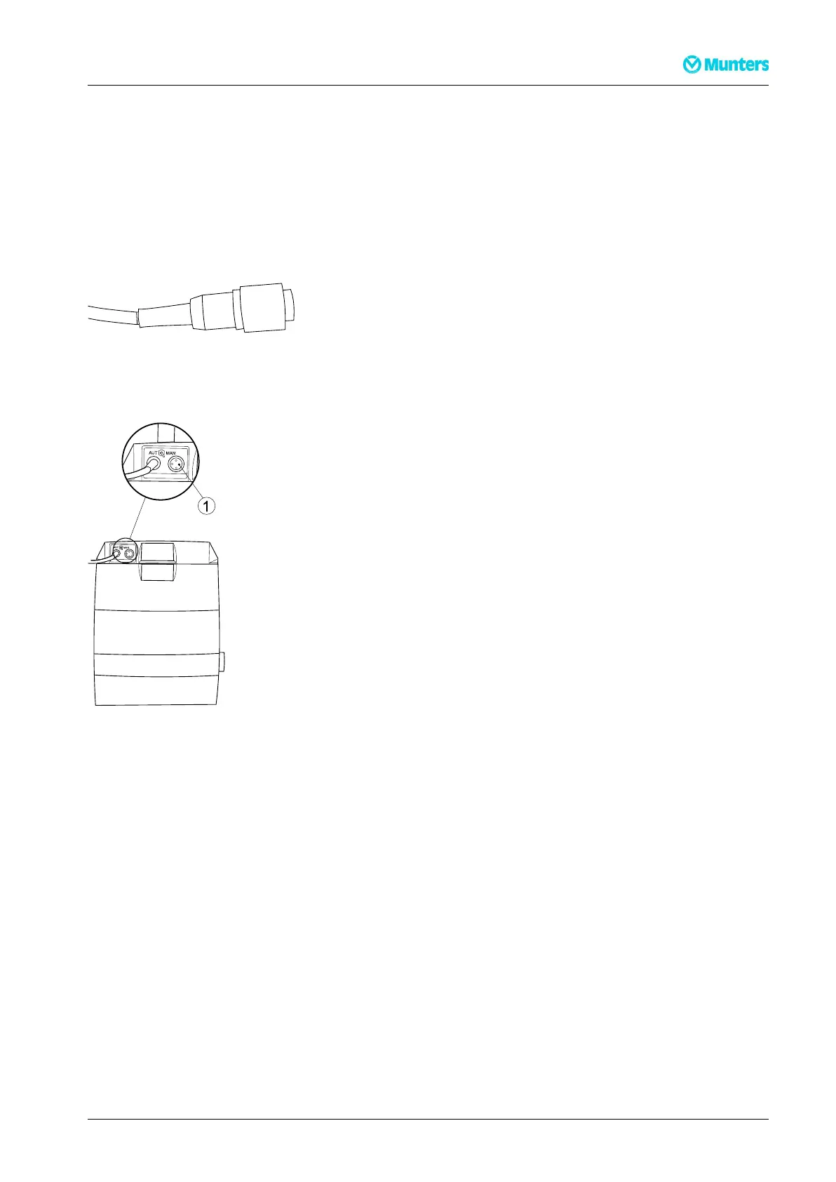
Figure4.11Connectorforhumidistatcable
Theconnectionsocketforthehumidistatislocatedonthefrontoftheunit.
Figure4.12Humidistatconnectionsocket(1)
Aroomhumiditysensoristobemounted1-1.5mabovetheoor.Itmustbepositionedsothatitisnot
directlyexposedtodryairfromtheunitortohumidairowinginthroughopeningdoors.Positionitaway
fromheatsourcesanddirectsunlight.
Thehumidistatmustbeasingle-stagehumidistatandconnectedsothatthecontrolcircuitcloseswhen
relativehumidityincreases.Theconnectioncablemustbescreenedandequippedwithacopperconductor
withaminimumcross-sectionareaof2x0.75mm
2
.
Iftheunitisusedtogetherwithanexternalhumidistat,operationmodeAorBcanbeused.
ModeA:ThehumidistatregulatestheentiredehumidierON/OFF(standardmode).
ModeB:Thehumidistatonlyregulatesthereactivationheaterandthefanoperatescontinuously.
ContactMuntersforchangingtheoperationmode.
190TGB-1004–N1402Installation12