Do you have a question about the Muratec MFX-1950 and is the answer not in the manual?
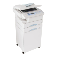
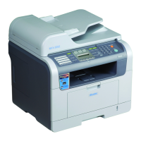
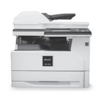
Describes the MFX-1950 and F-315 as multi-function products with flatbed scanner and facsimile capabilities.
Details the technical specifications of the MFX-1950 and F-315 models, including modem speed, scanning methods, and memory.
Presents a detailed block diagram illustrating the interconnection of various PCBs and components within the machine.
Explains the function of the main control PCB, its memory components (Flash, SRAM, SDRAM), and jumper settings.
Details the NCU PCB's role in connecting to the telephone line, including its interface circuit and control functions.
Describes the power supply unit's function, input voltage, output voltages, and connector outputs.
Illustrates the physical positions of various sensors attached to the machine's components.
Provides a brief explanation of each sensor's function, type, and any specific remarks.
Details the step-by-step process of document detection and scanning when using the Automatic Document Feeder (ADF).
Explains how paper is fed through the machine, including the path for duplex printing.
Describes the fundamental process of image creation within the machine.
Lists and describes various maintenance modes for machine adjustments, including commands and functions.
Explains how to program internal machine parameters using switches, with a backup battery maintaining settings.
Details how to program internal machine parameters using memory switches, with backup battery support.
Describes how to program unique switch settings, which are maintained by a backup battery.
Explains how to print a G3 procedural summary of the last fax communication.
Details how to access the printer maintenance mode for Fuser/Transfer roller replacement and error diagnosis.
Describes how to print a report containing machine usage and error history.
Explains how to turn on a mode to monitor fax communication signals through the machine's speaker.
Lists and describes various test modes available for diagnosing machine functions.
Instructs how to print lists of machine parameters, memory switch, and unique switch settings.
Explains how to print a list of available factory functions for machine testing.
Describes how to test the on/off operation of various relays and switches within the machine.
Explains the procedure for moving the mirror carriage to the transport position for shipping or installation.
Guides users on how to input dealer and customer information for printing or transmitting consumable order sheets.
Explains the procedure for clearing DRAM, recommended after memory upgrades or replacement.
Describes how to clear the life monitor counters for components like drums and toner cartridges.
Details how to clear all data and activity journals for the printer controller and second phone line.
Explains how to set a service code to protect the life monitor clear operation.
Describes how to confirm the status of various sensors by checking their values on the LCD.
Explains how to confirm the operation of individual parts of the printer section.
Guides on displaying the sum-check of the internet fax board for network troubleshooting.
Explains how to configure settings for an optional second line, including memory switches and ECM mode.
Describes how to check the Sum after updating the Flash ROM version for software integrity.
Guides on setting up the service report, including location, format, and sending period.
Explains how to adjust printer registration for each paper source.
Outlines the procedures for initial setup parameters, including consumable order and service report settings.
Details the process of installing the necessary software application on a PC for firmware updates.
Explains how to convert dialing characters for e-mail gateway transmissions using a web interface.
Provides a preliminary checklist for troubleshooting before starting unit checks or adjustments.
Addresses symptoms and corrective actions for paper jams occurring in the paper cassette or print area.
Covers symptoms and corrective actions for original documents not feeding or exiting properly from the document feeder.
Discusses issues where multiple pages are fed at once or documents are fed skewed in the ADF.
Explains symptoms and corrective actions for errors related to the mirror carriage not moving.
Addresses check messages that appear after attempting a transmission, referring to error code lists.
Details symptoms and corrective actions for black lines appearing on transmitted or copied documents.
Provides instructions for clearing paper jams in the ADF, including memory handling.
Addresses the symptom of blank pages and suggests causes like poor development or improper LED exposure.
Explains symptoms and potential causes for vertical white or black strips appearing on the image.
Describes symptoms of toner smudges and suggests corrective actions like cleaning ADF glass or fusing rollers.
Lists LCD error messages alphabetically with their meanings and suggested actions.
Explains specific error codes encountered during the dialing process, along with their meanings and solutions.
Addresses the "Call For Service" message and suggests checks for lamp and mirror carriage connections.
Provides a schedule for routine maintenance and replacement of parts for scanning, printer, and developing sections.
Details the removal and replacement procedures for various external covers of the machine.
Lists and shows the locations of various printed circuit boards within the machine.
Provides instructions for removing the roller separator, a part of the scanning mechanism.
Details the procedure for removing the solenoid, a component within the printer section.
Explains how to remove and replace the toner sensors (TS1, TS2) for the machine.
Provides an overview of the printer registration adjustment process for cassettes and scan positions.
Details the installation of an optional 32 MB document memory upgrade, including packaging and initialization.
Guides on the installation of an optional second paper cassette, including packaging and setup.
Explains the mechanical page counter, its function, and the installation process for the unit.
Details the installation of the PCL printer controller board, including packaging and connection steps.
Guides on installing the network interface board, including packaging and connection procedures.
Details the installation of a second phone line kit, including packaging and connection steps.
Explains the installation of the OfficeBridge Expansion kit for MFX-1950, including setup.
| Functions | Print, Copy, Scan, Fax |
|---|---|
| Print Technology | Laser |
| Print Speed (Black) | 19 ppm |
| Print Resolution | 600 x 600 dpi |
| Connectivity | USB, Ethernet, Wi-Fi |
| Display | LCD |
| Paper Capacity | 250 sheets |
| Automatic Document Feeder | Yes |
| Max Copying Resolution | 600 x 600 dpi |
| Fax Transmission Speed | 33.6 kbps |
| Scanner Resolution | 600 x 600 dpi |
| Paper Size | Letter, Legal, A4 |
| Copy Speed (Black) | 19 cpm |
| Type | All in One Printer |
| Max Copying Speed | 19 cpm |