5-20 5-20
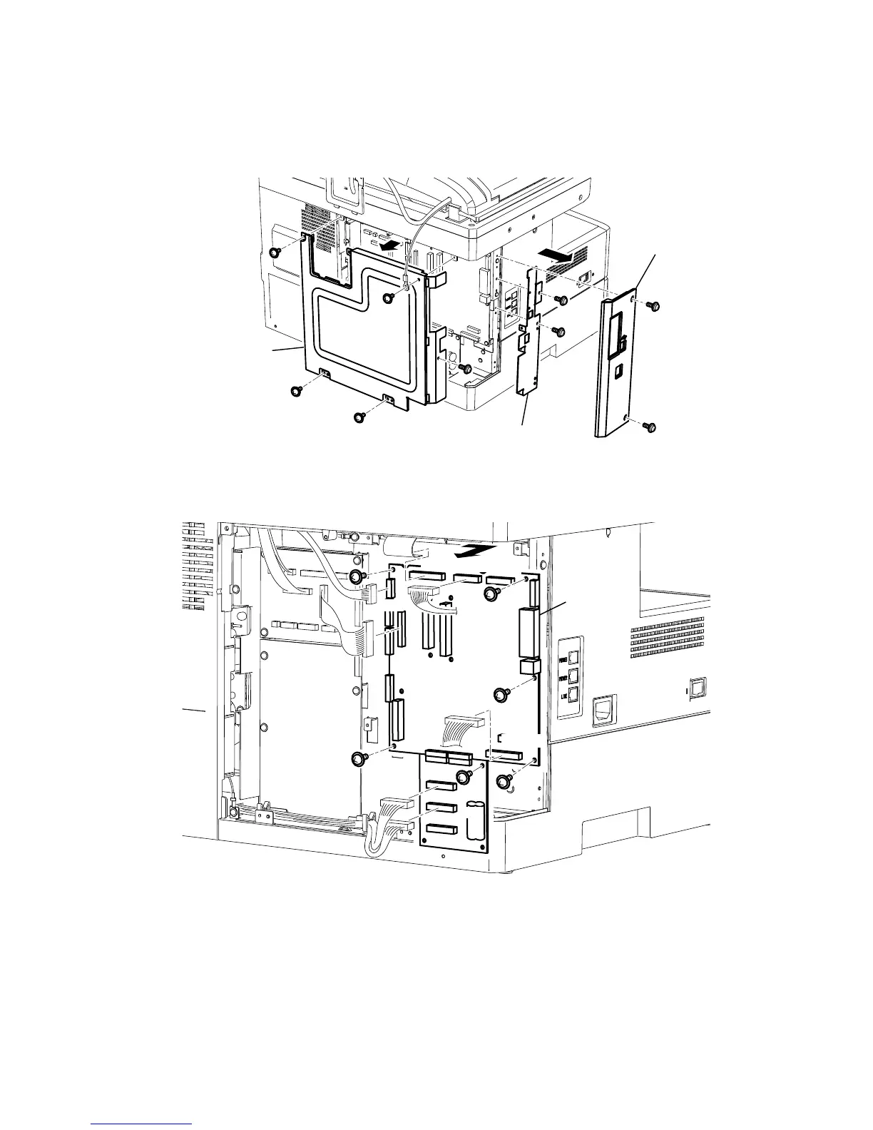
PCB MAIN
1. Remove the Cover connect and disconnect the connector. (See page 5-6)
2. Remove two Cover option mounting screws, and then remove the Cover option.
3. Remove four Cover shield mounting screws, and then remove the Cover shield.
4. Remove the Plate main B mounting screws, and then remove the Plate main B.
Cover option
Cover shield
Plate main B
5. Disconnect all connectors on the PCB MAIN.
6. Remove six PCB MAIN mounting screws, and then remove PCB MAIN.
P8C
P91
P92
P8C
P19
CCD
P5
PANEL
NCU
PCB MAIN
P3 PSU
Note: Turning parameters for Color(R,G,B) and Gray mode are stored in the EEPROM(IC42). When the PCB MAIN
is replaced, the EEPROM on malfunction PCB should be replaced to the new PCB.