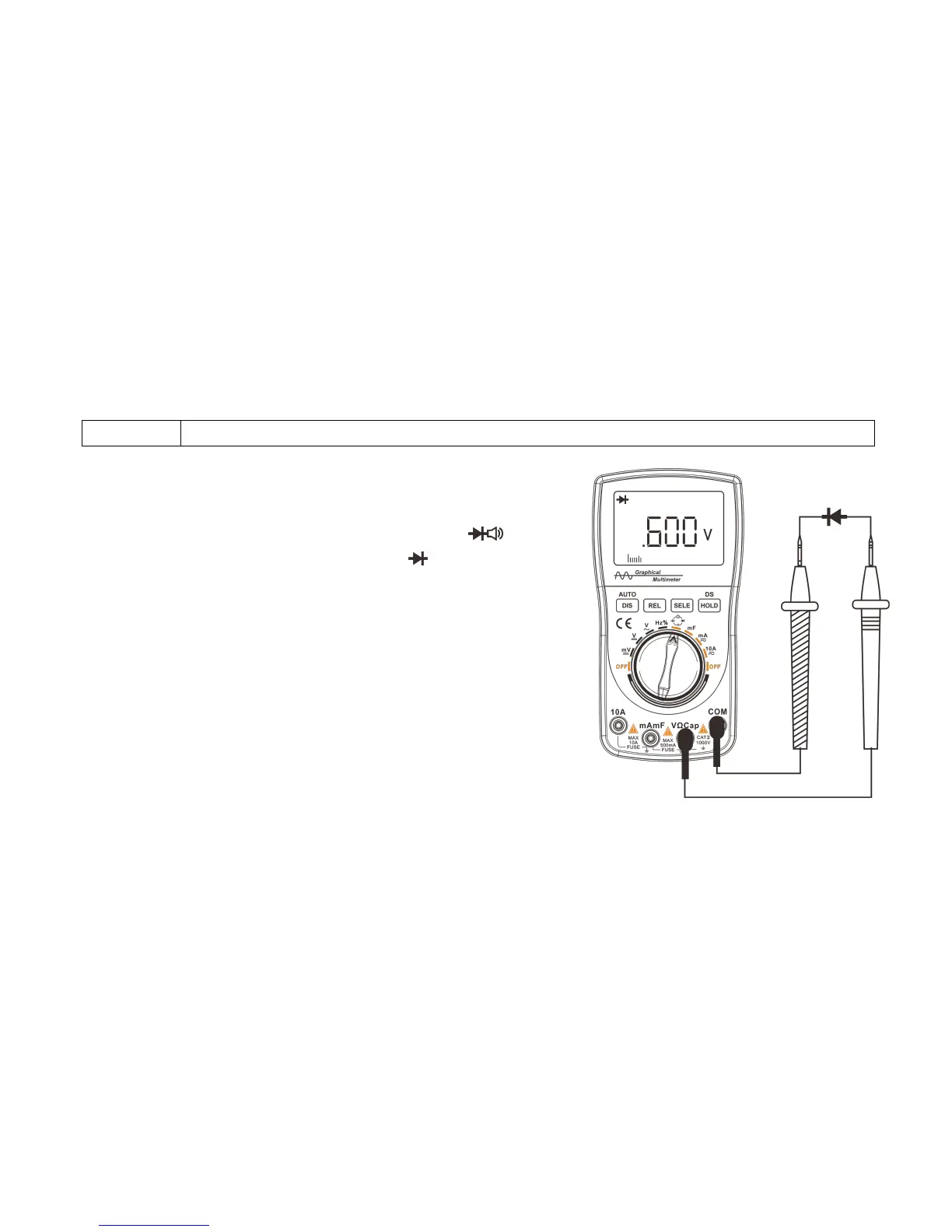
1. Insert the connecting plug of the black test probe into the negative
COM jack; insert the banana plug of the red test probe into
the positive resistance Ω jack.
2. Rotate the switch, point the arrow on the knob to the Ω Cap range,
and press the “SELE” button to switch to the range.
3. Connect the test probe to both ends of the diode or semiconductor’s
PN junction under test. Pay attention to the readings of the meter.
4. Swap the positions of the test probes to reverse the polarity.
Pay attention to the readings.
5. The nature of the diode or semiconductor’s PN junction can be
judged as follows:
If the reading in the first measurement is a voltage value
(approximately 0.2V to 0.7V), and the reading in the second
measurement shows “.0L”, the diode can be used normally.
If the readings in both measurements are “.0L”, the diode is opened circuited.
If the readings in both measurements are slight or ".000", the diode is shorted. Diagram of diode measurement