EasyManuals Logo

mycom 4032MSC User Manual

Default Icon
128 pages
To Next Page IconTo Next Page
To Previous Page IconTo Previous Page
Page #100 background imageLoading...
Page #100 background image
2201Q4JE-MY-C9-N_2018.01.
Chapter 5 Maintenance and Inspection
Compound 2-stage Screw Compressor 4032**C 5.5 Reassembly
5-55
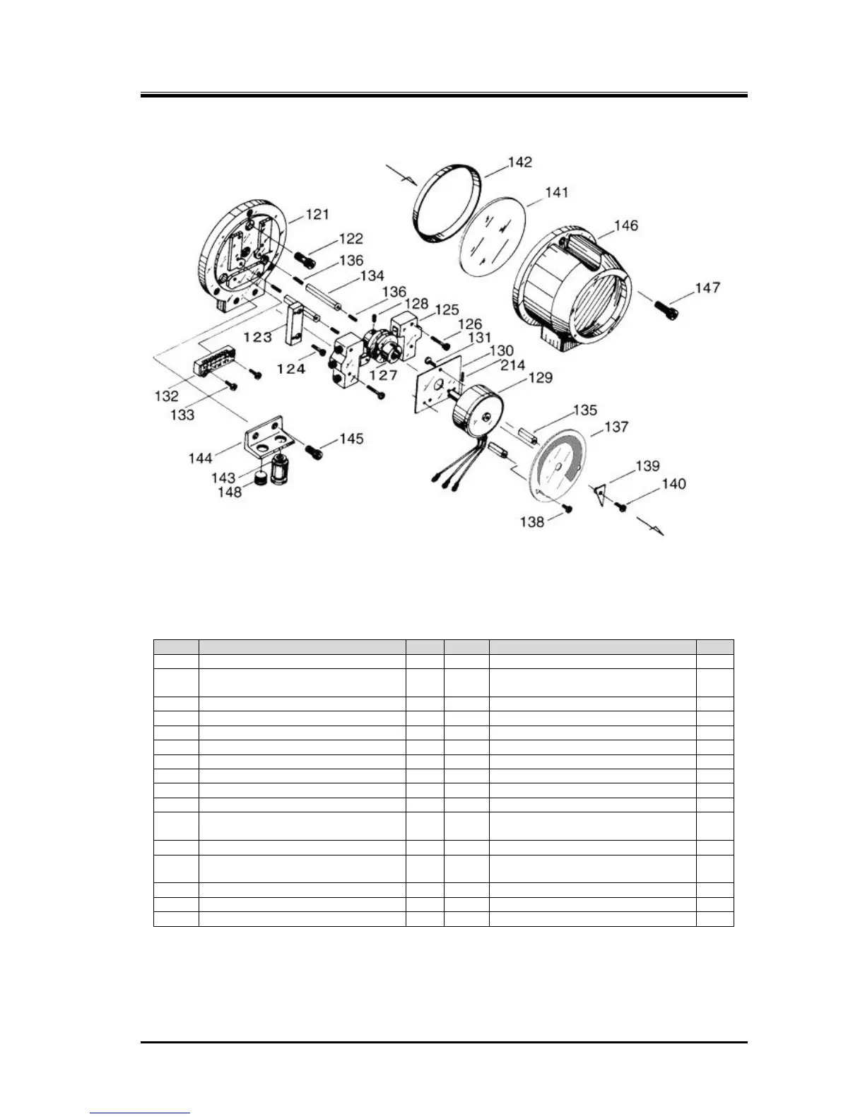
Figure 5-25 Unloader Indicator Assembly
Table 5-12 Component Parts of the Unloader Indicator Assembly
P/N
Part Name
Q'ty
P/N
Part Name
Q'ty
121
Micro-switch base plate
1
136
Hexagon socket set screw, M3 × 14
3
122
Hexagon socket head cap screw, M6
× 20
3
137
Dial, 30 to 100 %
1
123
Micro-switch base plate
1
137
Dial, 0 to 100%
1
124
Phillips Screw, M3 × 10
2
138
Phillips Screw, M3 × 5
2
125
Micro-switch
2
139
Indicator needle
1
126
Phillips Screw, M3 × 25
4
140
Phillips Screw, M3 × 10
1
127
Micro-switch cam, 30 to 100 %
1
141
Indicator glass
1
127
Micro-switch cam, 0 to 100 %
1
142
Indicator glass spacer
1
128
Hexagon socket set screw, M4 × 8
1
143
Electric cable gland
1
129
Potentiometer
1
144
Bracket, 125L
1
130
Potentiometer mounting plate
1
145
Hexagon socket head cap screw, M6
× 15
2
131
Phillips Screw, M3 × 5
3
146
Unloader indicator cover (2)
1
132
Terminal block
1
147
Hexagon socket head cap screw, M6
× 15
3
133
Phillips Screw, M3 × 20
2
148
Plug
1
134
Dial plate support [2]
2
214
Spring pin 2 dia. × 8
1
135
Dial plate support [1]
2
265-2
Spring washer, M3
7
Note: For the items 127 and 137, the range of 30 to 100% is specified for the high-stage and the
range of 0 to 100% is specified for the low-stage..

Table of Contents

Questions and Answers:

Question and Answer IconNeed help?

Do you have a question about the mycom 4032MSC and is the answer not in the manual?

mycom 4032MSC Specifications

General IconGeneral
Brandmycom
Model4032MSC
CategoryAir Compressor
LanguageEnglish

Related product manuals