EasyManuals Logo

mycom 4032MSC User Manual

Default Icon
128 pages
To Next Page IconTo Next Page
To Previous Page IconTo Previous Page
Page #124 background imageLoading...
Page #124 background image
2201Q4JE-MY-C9-N_2018.01.
Chapter 7 Related Documents
Compound 2-stage Screw Compressor 4032**C Tightening Torques for Bolts and Nuts
7-13
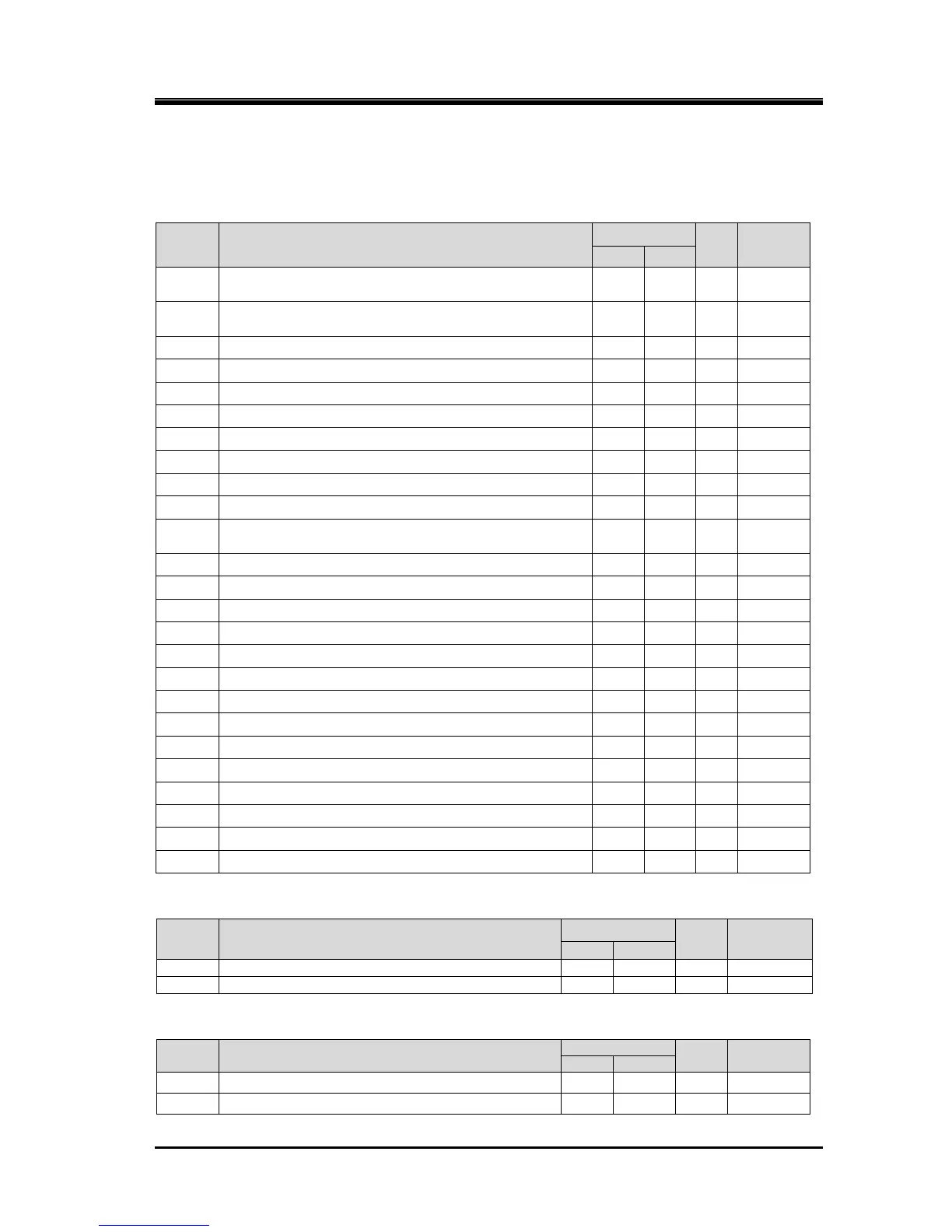
7.3 Tightening Torques for Bolts and Nuts
Table 7-2 List of Tightening Torques
Hexagon socket head cap screw
P/N
What is tightened
Torque
Qty.
Size
N·m
kgf·cm
2-1
Main Rotor Casing (1) to
Suction Cover (1) and Bearing Head (1)
1600
16000
60
M30×110
2-2
Main Rotor Casing (2) to
Suction Cover (2) and Bearing Head (2)
750
7500
52
M24×80
18-1
Bearing Cover to Bearing Head (1)
1600
16000
22
M30×100
18-2
Suction Cover (1) to Bearing Head (2)
750
7500
22
M24×75
18-3
Suction Cover (1) to Bearing Head (2)
750
7500
4
M24×95
24
Balance Piston Cover to Suction Cover (2)
240
2400
11
M16×45
53
Seal Cover to Bearing Cover
240
2400
8
M16×40
58-1
Unloader Push Rod (1) to Unloader Slide Valve (1-1)
140
1400
8
M14×55
58-2
Unloader Slide Valve (2-2) to Unloader Slide Valve (1-2)
240
2400
4
M16×50
61
Unloader Cylinder (2) to Balance Piston Cover
450
4500
2
M20×50
62
Unloader Cylinder (2) to
Balance Piston Cover and Suction Cover (2)
450
4500
6
M20×110
76-1
Unloader Cover (1) to Unloader Cylinder (1)
640
6400
8
M22×70
76-2
Unloader Cover (2) to Unloader Cylinder (2)
240
2400
8
M16×40
81-1
Bearing Gland (1) to Unloader Cover (1)
10
100
3
M6×15
81-2
Bearing Gland (2) to Unloader Cover (2)
10
100
3
M6×15
159
Shaft Key for Drive Hub
50
500
2
M10×25
166-1
Oil Gland (1) to Bearing Head (1)
90
900
4
M12×25
166-2
Oil Gland (2) to Bearing Head (2)
6
60
4
M5×12
212-A
Indicator Fixture (A) to Unloader Cover (1)
25
250
2
M8×30
212-B
Indicator Fixture (A) to Unloader Cover (1)
25
250
2
M8×95
212-C
Indicator Fixture (B) to Indicator Fixture (A)
25
250
4
M8×20
247-1
Unloader Slide Valve Guide to Main Rotor Casing(1)
240
2400
8
M16×75
594
Bearing Cover to Unloader Cylinder (1)
450
4500
12
M20×75
595-A
Bearing Cover to Bearing Head (1)
750
7500
10
M24×110
595-B
Bearing Cover to Bearing Head (1)
450
4500
2
M20×110
Hexagon Head Bolt
P/N
What is tightened
Torque
Qty.
Size
N·m
kgf·cm
45-1
Thrust Bearing Gland (1)
120
1200
8
M20×55
45-2
Thrust Bearing Gland (2)
60
600
8
M145
Stud Bolt and Hexagonal Nut
P/N
What is tightened
Torque
Qty.
Size
N·m
kgf·cm
97-1
Low-stage Gas Outlet Flange (Intermediate Pipe)
200
2000
16
M20×75
97-4
High-stage Gas Inlet Flange (Intermediate Pipe)
200
2000
16
M20×55

Table of Contents

Questions and Answers:

Question and Answer IconNeed help?

Do you have a question about the mycom 4032MSC and is the answer not in the manual?

mycom 4032MSC Specifications

General IconGeneral
Brandmycom
Model4032MSC
CategoryAir Compressor
LanguageEnglish

Related product manuals