2201Q4JE-MY-C9-N_2018.01.
Chapter 5 Maintenance and Inspection
Compound 2-stage Screw Compressor 4032**C 5.5 Reassembly
5-43
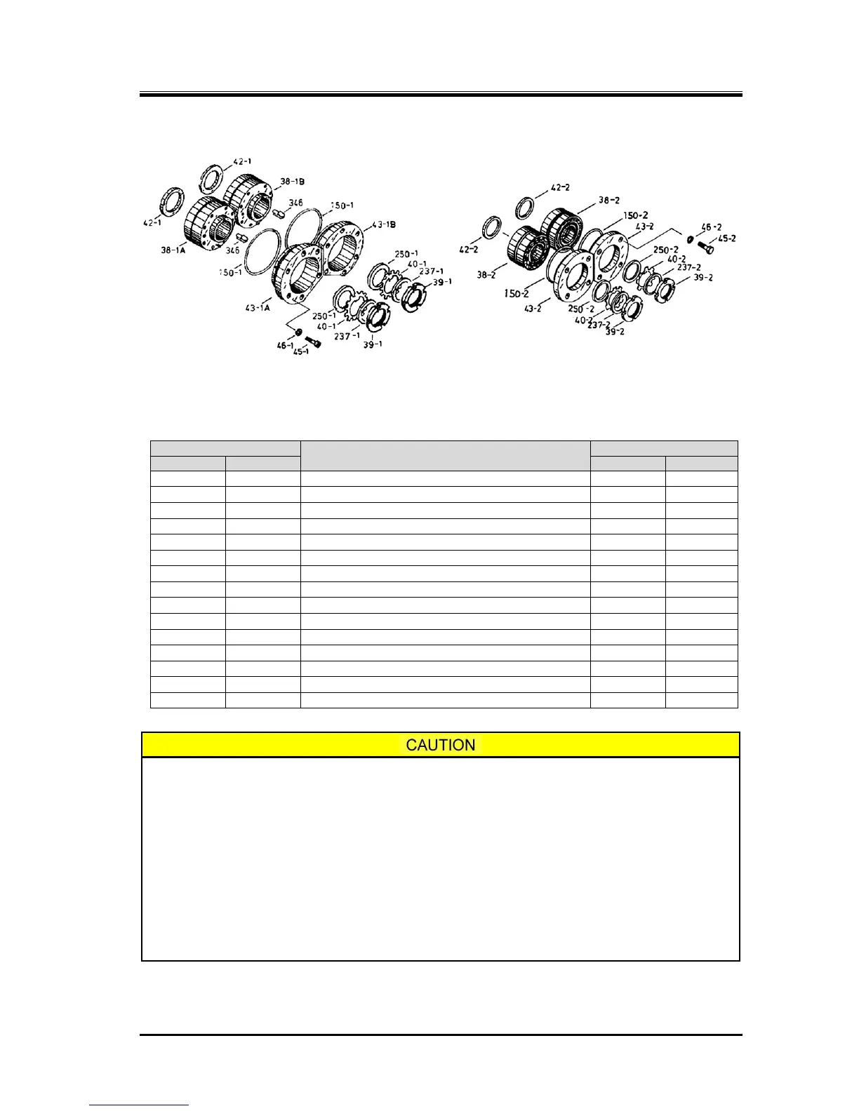
5.5.8 Thrust Bearing Block
[Low-stage] [High-stage]
Figure 5-20 Thrust Bearing Block
Table 5-10 Components of the thrust bearing block
Thrust bearing alignment spacer (1), (2)
Thrust bearing (1), M rotor, (2)
Thrust bearing (1), F rotor
Thrust bearing gland (1A), (2)
Thrust bearing gland (1B)
Torsional slip washer (1), (2)
Spring washer, hexagon socket head cap screw
Conical spring washer (2)
Hexagon socket head cap screw (1)
The torsional slip washer [237] and lock washer [39] must be replaced with new ones.
If the removed thrust bearing is to be installed as it is, check the marking of "M" or
"F" on the thrust bearing alignment spacer and assemble it in the same combination
as it was disassembled. This is important in controlling the end clearance on the
discharge side of the rotor.
Even if the same bearing is installed, the work must be very carefully done as the
dimension can change if any foreign matter such as a chip of paint or dust is pinched
by the alignment spacer.
In determining the installation direction of the thrust bearing, there are two methods
depending on the existence of an alignment "V" marking on the outer circumference
of the bearing. Install the bearing according to the following procedure provided for
each case.