2201Q4JE-MY-C9-N_2018.01.
Chapter 3 Installation
Compound 2-stage Screw Compressor 4032**C 3.2 Installation Works
3-4
3.2.4 Preparation for Installation
Installation Space
Secure sufficient working space for easy operation, cleaning, maintenance, and inspection.
Illumination
Prepare illumination devices which allow easy operation, cleaning, maintenance, and inspection.
Ventilation
If natural ventilation is insufficient, install ventilation fans according to the relevant regulations.
Piping
Table 3-1 List of Connecting Pipes (Compressor)
High-stage discharge gas outlet
Lubricating oil inlet for low-stage TPTB
Lubricating oil inlet for low-stage main
bearing
Lubricating oil inlet for low-stage side
bearing
Oil inlet for oil injection
Lubricating oil inlet for high-stage bearing
Oil outlet of low-stage suction cover
Oil outlet of low-stage bearing head
Oil outlet of high-stage suction cover
Lubricating oil inlet for low-stage capacity
control (load)
Lubricating oil inlet for low-stage capacity
control (unload)
Lubricating oil inlet for high-stage capacity
control (load)
Lubricating oil inlet for high-stage capacity
control (unload)
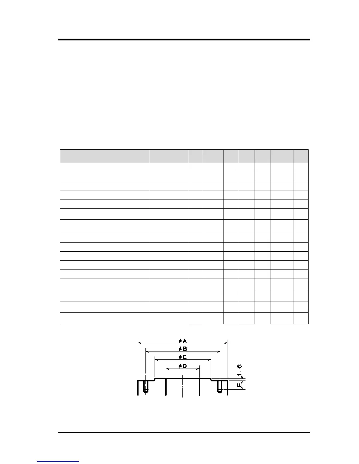
Figure 3-2 Dimensions of the Joint (Compressor)
for the ANSI #300 Flange