2201Q4JE-MY-C9-N_2018.01.
Chapter 5 Maintenance and Inspection
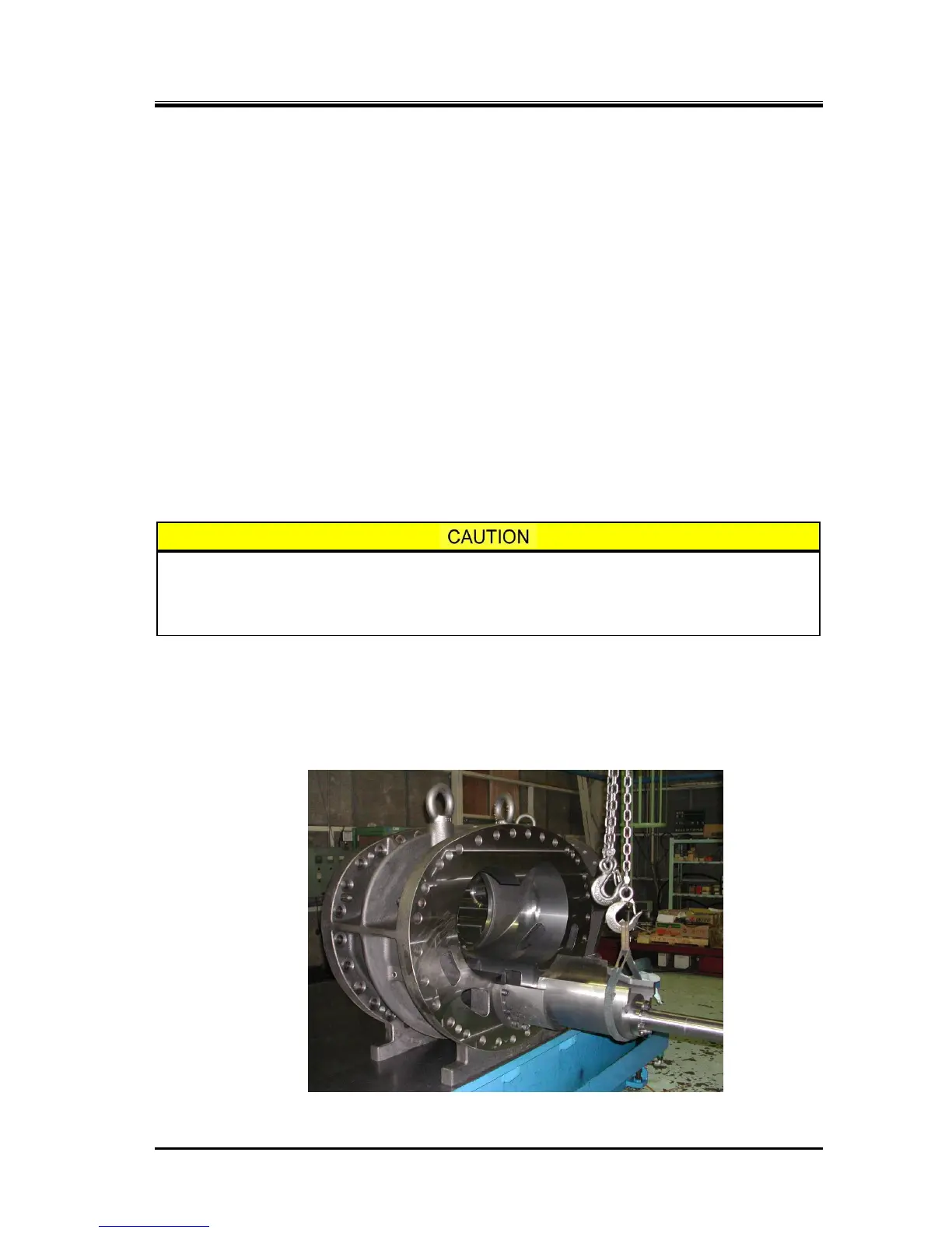
Compound 2-stage Screw Compressor 4032**C 5.5 Reassembly
5-35
5.5.1 Unloader Slide Valve
a) Attach two O-rings [89] on the guide block stem [88] and screw in the guide block stem securely
from the bottom of the main rotor casing [1]. Then, mount the guide block [87] in the casing.
In the case of 4032**C models, the guide block is not used in the low-stage main rotor casing.
b) If the slide valve assembly has been disassembled, first make sure that the alignment position
between the unloader slide valves [54] and [55] is accurately reproduced and then tighten the
hexagon socket head cap screws [58] with spring washers [267] at the specified torque. The outer
diameter of the spring washers used here is less than normal spring washers for hexagon socket
head cap screws. So, be careful not to mix up with other washers.
In the case of 4032**C models, the unloader slide valve [55] is only used in high-stage side.
c) After using a grind stone or fine sand paper to lightly finish the circumference of the assembly,
mount the assembly in the main rotor casing using a crane or like.
In the high-stage side, slowly push-in the slide valve while aligning the groove of the slide valve
with the guide block.
d) After it is assembled, hold the unloader push rod and move it for several times to check that it
moves smoothly. Then, carefully check the joint with the casing that there is no step between them.
◆ A slight step between the surfaces of the unloader slide valve and the casing is allowed if the
slide valve side is lower.
If the step is such that the surface of the unloader slide valve is higher than the
surface of the rotor casing, it is considered the problem of assembly. In such a case,
it must not be left uncorrected. Be sure to reassemble it. Otherwise, the periphery of
the rotor can make contact with the slide valve, resulting in a severe damage.
e) The low-stage slide valve assembly has a external snap ring [661] not to move the slide valve
toward the bearing head exceeding the necessary position (i.e., indicated load 0%).
If you remove this snap ring [661] at the time of disassembly,, never forget to attach the snap ring.
Without this snap ring, it may occur the incident that the slide valve assembly will not move toward
loading direction.