2201Q4JE-MY-C9-N_2018.01.
Chapter 5 Maintenance and Inspection
Compound 2-stage Screw Compressor 4032**C 5.4 Disassembly and Inspection
5-15
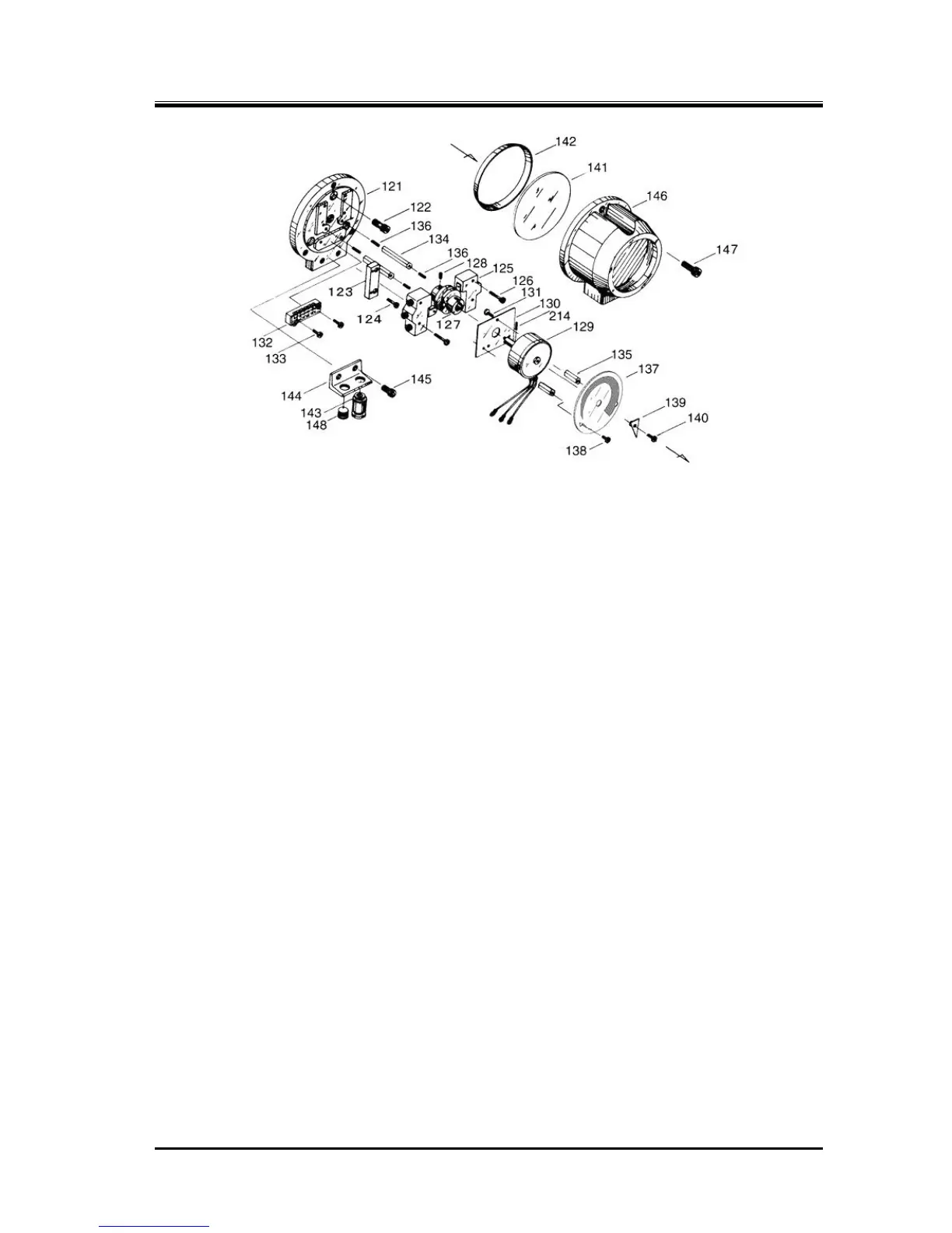
Figure 5-4 Standard type Unloader Indicator
5.4.1.1 Disassembly
■ In Case of Removing the Wiring only
When removing the wiring of the unloader indicator upon removing the compressor, it is necessary
to remove the cover as the indicator has a terminal block for the wiring. Perform the work according
to the following procedure, and after removing the wires, attach the cover to them for protection.
The structure of an unloader indicator assembly is the same as both low-stage and high-stage.
a) By removing the three hexagon socket head cap screws [147] that are used to fasten the
indicator cover [146], the cover can be removed.
b) The indicator cover will be removed with the glass [141] and spacer [142] attached. While the
glass and spacer are glued, be careful not to drop these as they may be separated from the
cover.
c) Remove the plastic plate on the terminal block, and then remove the wiring.
Apply vinyl insulation tape to the wiring terminals, and paint identification numbers to prevent
them from being mixed up at recovery.
■ When removing unloader indicator assembly parts, with the wiring left as it is
Steps a) and b) are the same as described above.
c) Loosen the cam set screw [128] which secures the micro-switch cam [127] on the shaft of the
indicator cam [77-2] on the high-stage side, or on the shaft of the indicator bar [208] of the
indicator fixture on the low-stage side.
d) Loosen and remove the hexagon socket head cap screws [122] fastening the micro switch
mounting plate [121] to the unloader cover [74-2] on the high-stage side, or to the indicator
fixture on the low-stage side.
e) Now, the assembly can be pulled out as it is in the axial direction.
5.4.1.2 Inspection
The inspection procedure is described in the "Reassembly" section of this chapter, as it is often the
case that the unloader indicator block is removed as an assembly and later inspected and adjusted
after the overhauled compressor is reassembled and installed on the mounting base. Refer to Section
5.5.15 "Unloader Indicator" for details.