2201Q4JE-MY-C9-N_2018.01.
Chapter 5 Maintenance and Inspection
Compound 2-stage Screw Compressor 4032**C 5.4 Disassembly and Inspection
5-14
5.4.1 Unloader Indicator
On the 4032**C model, unloader indicators are installed on both the high and low-stages.
The high-stage unloader has the same indicator as that for the UD-series single-stage
compressors (standard model), while the dial and the micro-switch cam are designed for indicated load
of 30 to 100 %.
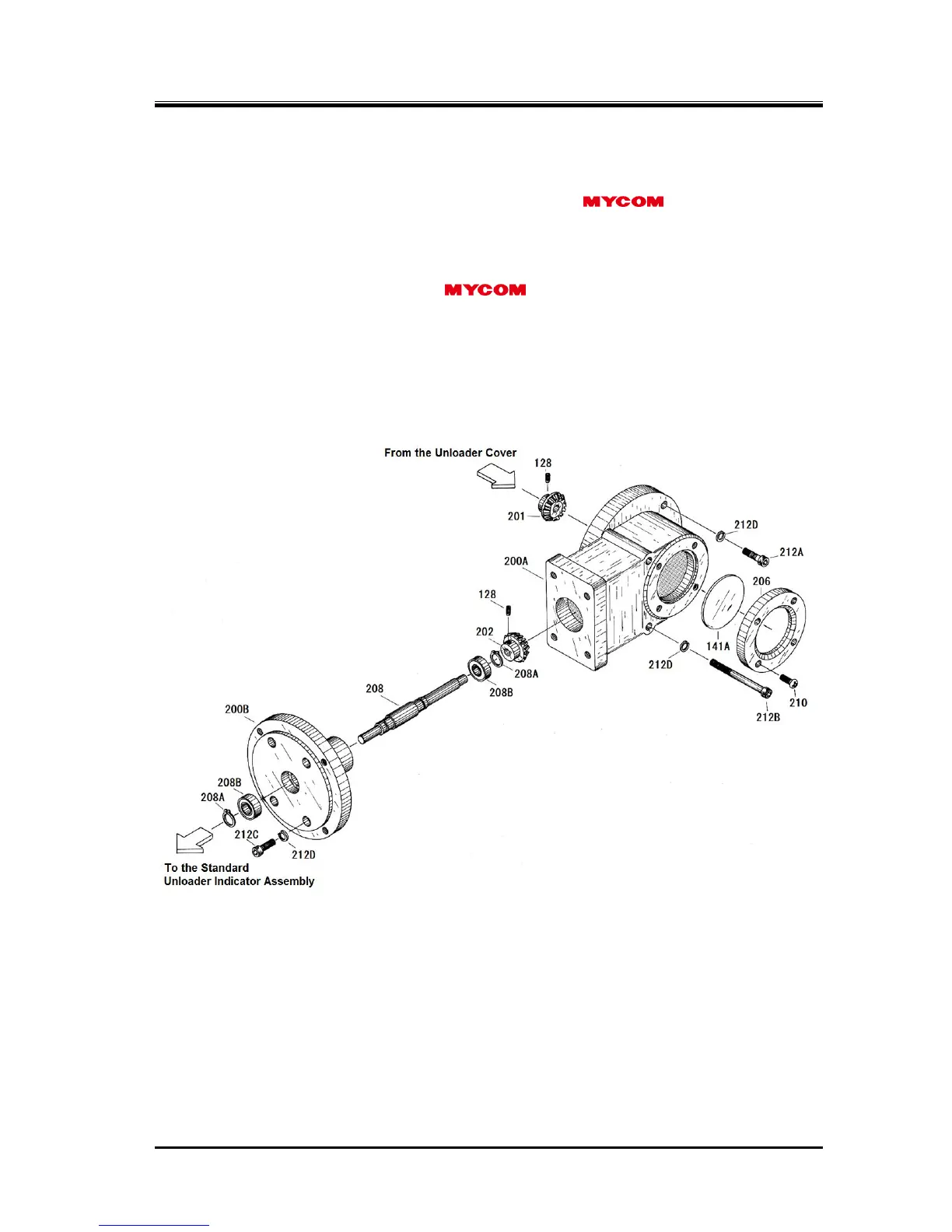
On the low-stage side to be easy to see the indicator dial, the standard indicator assembly is attached
with a fixture for 4032**C model that bends the indicator by 90° clockwise or counterclockwise viewed
from either of the rotor shaft ends. In the C-series compressor models, 2520**C and
4032**C are made in this structure using "Unloader indicator fixture assembly" and "Standard type
unloader indicator assembly" as a low-stage unloader indicator.
The unloader indicator assembly has a potentiometer, two micro switches, a micro switch cam, a set of
retainers, micro-switch mooting plate, indicator pointer with dial and terminal block.
Figure 5-3 4032**C Low-stage Unloader Indicator Fixture Assembly