EasyManua.ls Logo

mycom 4032MSC

Default Icon
128 pages
To Next Page IconTo Next Page
To Previous Page IconTo Previous Page
Loading...
2201Q4JE-MY-C9-N_2018.01.
Chapter 7 Related Documents
Compound 2-stage Screw Compressor 4032**C About the O-rings Used
7-15
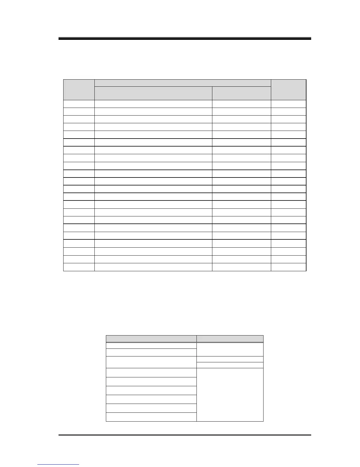
7.4 About the O-rings Used
7.4.1 List of O-rings Used
Table 7-4 List of O-rings Used
O-ring
Part No.
Location
JIS B 2401
Size
attached place
description in
functional aspect
9
O-ring Gland
same as left
G95
35
Balance Piston Sleeve
same as left
G190
63-1
Unloader Cylinder (1)
same as left
G250
63-2
Balance Piston Cover
Unloader Cylinder (2)
G240
65-1
Unloader Piston (1)
same as left
P215
65-2
Unloader Piston (2)
same as left
P200
73-1
Unloader Push Rod (1)
Unloader Piston (1)
G45
73-2
Unloader Push Rod (2)
Unloader Piston (2)
P44
75-1
Unloader Cover (1)
same as left
G220
75-2
Unloader Cover (2)
same as left
G210
89-2
Guide block Stem (2)
same as left
P24
150-1
Thrust Bearing Gland (1)
same as left
G290
150-2
Thrust Bearing Gland (2)
same as left
G220
163
Unloader Push Rod (1)
same as left
G65
325
O-ring Gland (1)
same as left
P70
328
O-ring Gland (2)
same as left
P58
421
Unload Spacer (2)
same as left
P58
432-1
Main Bearing (1)
same as left
G200
432-2
Main Bearing (2)
same as left
G165
433-1
Side Bearing (1)
same as left
G200
433-2
Side Bearing (2)
same as left
G165
674
Seal Cover for BOD type Mechanical Seal
same as left
Note2
Note 1: Attached place means parts which they have grooves or with taper cutting for attaching O-ring.
Note 2: AS568A 261Old JIS W1516 G39
7.4.2 O-ring Materials Used for Screw Compressor
Table 7-4 List of O-ring Materials Used for Screw Compressor
(excluding mechanical seal)
Working fluid
O-ring material
Ammonia
NBR
HFC
CO
2
FKM
HNBR
R23
FKM
Propane
Propylene
Natural gas
City gas
Helium

Table of Contents

Related product manuals