2201Q4JE-MY-C9-N_2018.01.
Chapter 5 Maintenance and Inspection
Compound 2-stage Screw Compressor 4032**C 5.5 Reassembly
5-38
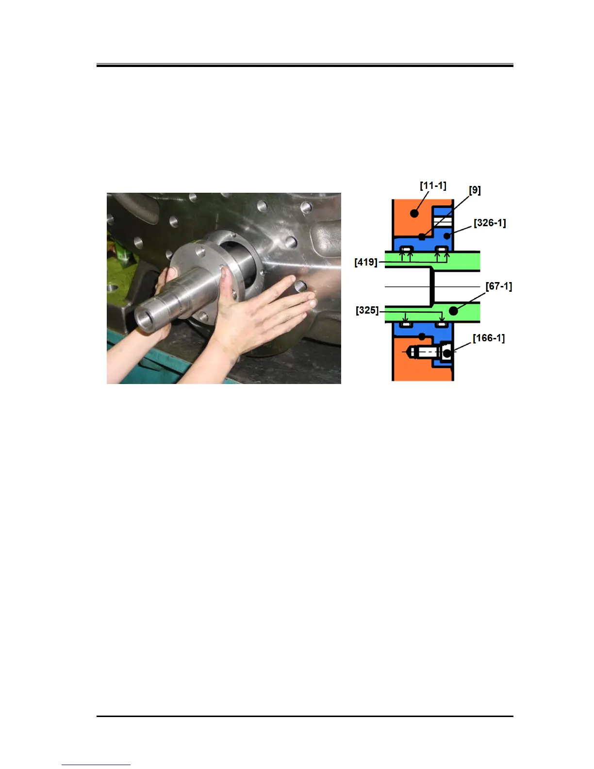
g) Attach the O-ring gland [326-1] on the low-stage bearing head where is the part of the unloader
push rod protruding.
Attach two O-rings [325] and four backup rings [419] alternately on the two O-ring grooves in the
O-ring gland inner circumference.
h) Also attach the O-ring [9] on the O-ring groove of the O-ring gland outer circumference.
i) Then, mount the O-ring gland on the unloader push rod and push it into the bearing head [11-1].
Figure 5-18 Low-stage O-ring Gland
j) Tighten the O-ring gland to the low-stage bearing head using four hexagon head cap screw [166-1].
k) Attach the O-ring [73-1] on the tip of the unloader push rod.