3
EN
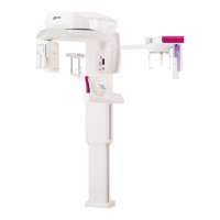
hyperion X5 2D/3D - TECHNICAL MANUAL
DEVICE INSTALLATION
1. DEVICE INSTALLATION
1.1 REQUIRED INSTRUMENTS
All the device installation procedures are described in the videos uploaded on the extranet. The following instruments
are necessary to perform all the procedure properly:
Allen wrench set
Screwdrivers
Scissors
Spirit level
Electric cable
Threaded bars or bolts
Network cables
RJ12 telephone cable
Calibration kit
WARNING: After mechanical installation, check that:
1 - kinematic mechanism is securely fastened to the column and that it does not swing. Check that the
6 M8 xing screws (2 side and 4 front screws) are fully tightened.
2 - In case of stand installation: the column must be securely fastened and there should be no clea-
rance.
3 - In case of wall installation: the column must be securely anchored to the wall (check bolts or
counter-plate) and there should be no clearance.
In case of column vibrations check the following:
1 - If the device is in AIR version: check that the screws fastening the column to the wall are not too tightened and the
feet are adjusted so that the column is levelled and is not affected by torsion. If required, loosen 2 of the 4 xing
screws (in a cross pattern from top right to bottom left, or vice versa) so that the column has a little clearance. Adjust
the feet to make the column rest against the wall.
2 - If the device is fastened both to the wall and to the oor: check that the column is not affected by torsion. Loosen the
screws fastening it to the ground to allow a little clearance to the column. In order to position the column correctly
move it a couple of times to adjust it, then secure it to the oor.
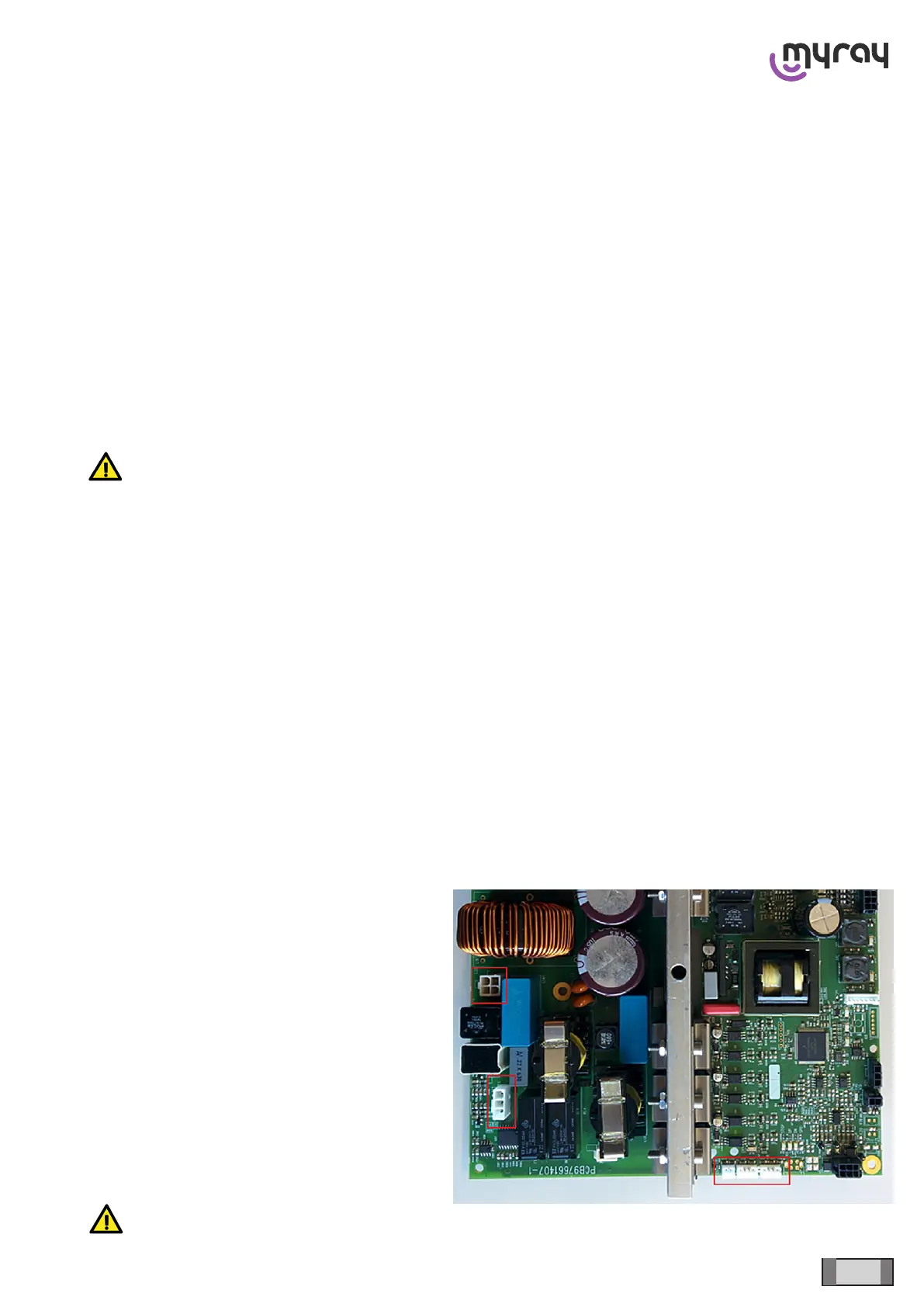
1.2 INTERNAL CONNECTIONS
Once the device has been installed, connect the column cables to the kinematic unit:
There are 5 connectors that have to be connected
to the power board:
K1 Column motor
K2 Column motor thermal sensor
K13 Column upper end stop photocell
K18 Column lower end stop photocell
K22 Anti-crushing microswitch
WARNING: check the photocell connections; DO NOT reverse K13 and K18!