The distance between the outer edge of the casing
and
the bearing outer race must be measured and,
if
re-
quired, adjusted to the correct dimension by
means
of
spacers.
A
distance from
0.3
to
0.3
mm to the cover plate must
remain. Thc thickness of the original packing
(0.5
mm)
must bc takcn into account. Find out whether the
spacel- bush
(1)
has been damaged by the sealing
lip
and check that thc scaling ring is in perfect working
condition.
Propcrlg clcan thc joint surface of the cover plate,
inscrt
a
pnpcr packing (use jointing compound). and
(ich~c~~
t
lie sc~~\\.s clms\vise [Torque 4.9Nm
(0.5
kpm)].
Placc
thc
cnfiinc
;n
upright pobition
-
if there is no
assen~blin~ faull (Flgs.
44
to
46).
the crankshaft must
be free to bc mo\.c,d \vith case.
By
\$.ay of trial. shift the gears of the gearbox
-
a:
the same time turn thc clutch shaft.
The clutch shaft must be free to move easily; if this
is not the case. use a rawhide mallet to drive the shaft
(lower
arrou7) for\rnrd through a distance of
0.2
mm
and then use
a
coppci. mandrel (placed..through the
Fig
49.
Aligning
tlle
gearbox
shaft wheel) to beat the shaft back (upper arrow). Now
the end clearance shown in Fig.
38
between the face
of the keyway section of the clutch shaft and the shaft
wheel must be present.
Slightly grease the lip of the sealing ring
in
the cover
i
plate
-
put on the distance bush
[(I)
in Fig.
481.
I
Fit the gearbox sprocket (recess pointing to the engine)
I
and lock plate. Tighten the nut with a width over
flats of
27
with
58,9
Nm
(6
kp-m) (l eft
-
h a n d
t
h
r
e a d
)
and flt the lock plate.
Arrest the assembly with the
05-MW 45-3
holder or an
old chain.
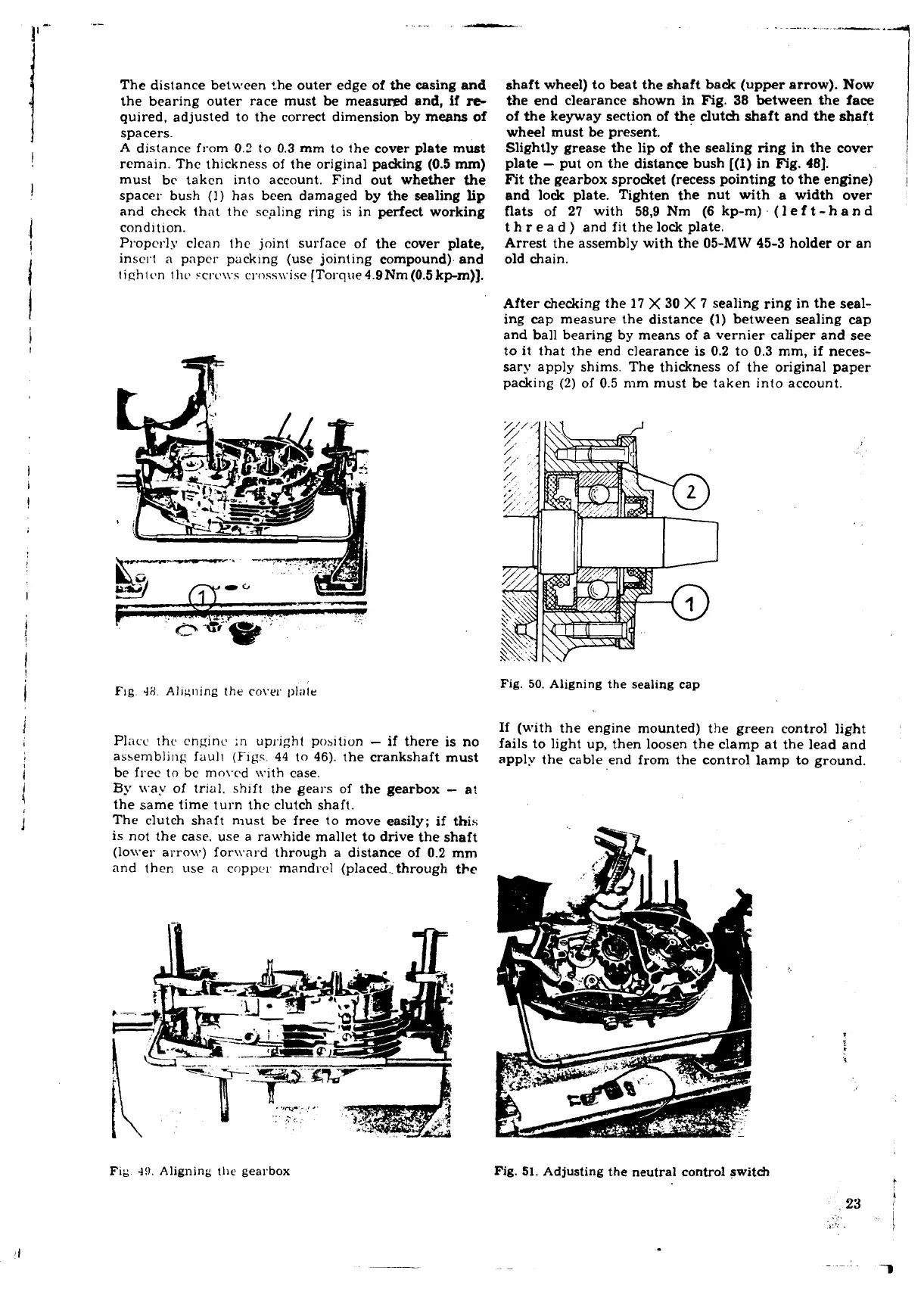
After checking the
17
X
30
X
7
sealing ring in the seal-
ing
cap
measure the distance
(1)
between sealing cap
and ball bearing by means of a vernier caliper and see
to it that the end clearance is
0.2
to
0.3
mm, if neces-
sary apply shims. The thickness of the original paper
packing
(2)
of
0.5
mm must be taken into account.
Fig.
50.
Aligning the sealing cap
If
(with the engine mounted) the green control light
fails to light up, then loosen the clamp at the lead and
apply the cable end from the control lamp to ground.
Fig.
51.
Adjusting the neutral control switch
I
 Loading...
