arm bearing pins. It may
be
the rear wheel that causes
these troubles in the front fork.
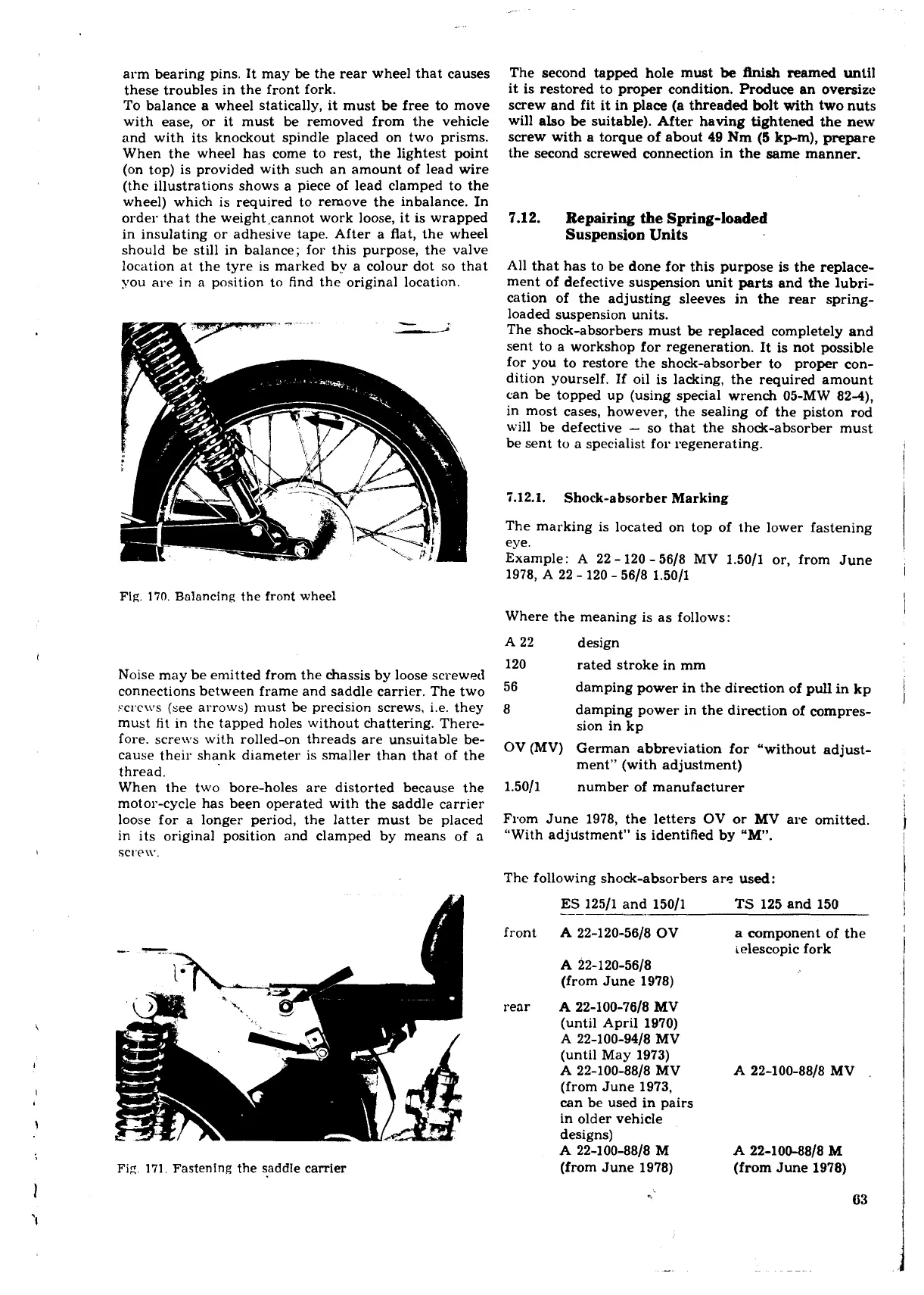
To balance a wheel statically, it must be free to move
with ease, or it must be removed from the vehicle
and with its knockout spindle placed on two prisms.
When the wheel has come to rest, the lightest point
(on top) is provided with such an amount of lead wire
(the illustrations shows a piece of lead clamped to the
wheel) which is required to remove the inbalance. In
order that the weight,cannot work loose, it is wrapped
in insulating or adhesive tape. After a flat, the wheel
should be still in balance; for this purpose, the valve
location at the tyre is marked by a colour dot so that
you are in
a
position to find the original location.
The second tapped hole must
be
Aniah
reamed until
it is restored to proper condition. Produce an oversize
screw and fit it in place (a threaded bolt with two nuts
will also
be
suitable). After having tightened the new
screw with a torque of about 49 Nm
(5
kpm), prepare
the second screwed connection in the same manner.
7.12.
Repairing the Spring-loaded
Suspension Units
All that has to be done for this purpose is the replace-
ment of defective suspension unit parts and the lubri-
cation of the adjusting sleeves in the rear
spring-
loaded suspension units.
The shock-absorbers must
be
replaced completely and
sent to a workshop for regeneration. It is not possible
for you to restore the shock-absorber to
proper con-
dition yourself. If oil is lacking, the required amount
can be topped up (using special wrench 05-MW 82-4),
in most cases, however, the sealing of the piston rod
will be defective
-
so that the shock-absorber must
be sent to a specialist for regenerating.
5.12.1.
Shock-absorber Marking
The marking is located on top of the lower fastening
eye.
Example: A 22
-
120
-
5618 MV 1.5011 or, from June
1978, A 22
-
120
-
5618 1.5011
Fig.
170.
Balancing the front wheel
Where the meaning is as follows:
Noise may be emitted from the chassis by loose screwed
connections between frame and saddle carrier. The two
xl.c\vs (see arrows) must be precision screws, i.e. they
must
fit
in the tapped holes without chattering. Therc-
fore. scre\i8s with rolled-on threads are unsuitable be-
cause their shank diameter is smaller than that of the
thread.
When the two bore-holes are distorted because the
motor-cycle has been operated with the saddle carrier
loose for a longer period, the latter must be placed
in its original position and clamped by means of a
SCtF\V,
Fig.
171.
Fastening the saddle carrier
A 22 design
120 rated stroke in mm
56
damping power in the direction of pull in kp
8
damping power in the direction of
compres-
sion in kp
OV (MV) German abbreviation for "without adjust-
ment" (with adjustment)
1.5011 number of manufacturer
From June 1978, the letters OV or MV are omitted.
"With adjustment" is identified by
"M.
The following shock-absorbers are used:
front
rear
ES
12511 and 15011
TS
125 and 150
A 22-120-5618 OV
a component of the
ielescopic fork
A
22-120-5618
(from June 1978)
A 22-100-7618 MV
(until April 1970)
A
22-100-9418 MV
(until May 1973)
A
22-100-8818 MV
A
22-100-8818
MV
(from June 1973,
can be used in pairs
in older vehicle
designs)
A
22-100-8818 M
A
22-100-8818
M
(from June 1978)
(from June 1978)