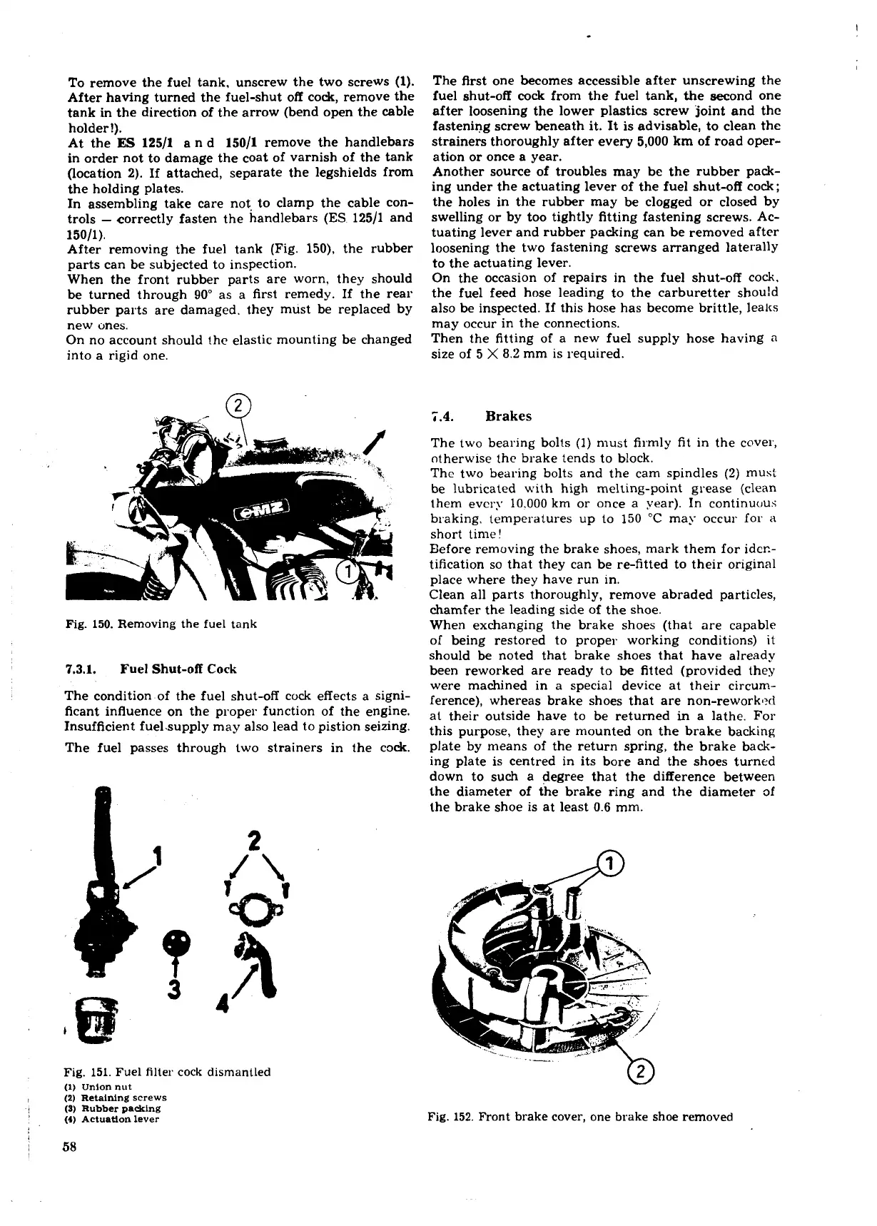
To remove the fuel tank, unscrew the two screws
(1).
After having turned the fuel-shut off cock, remove the
tank in the direction of the arrow (bend open the cable
holder!).
At the
ES
12511
a n d 15011 remove the handlebars
in order not to damage the coat of varnish of the tank
(location 2). If attached, separate the legshields from
the holding plates.
In assembling take care not to clamp the cable con-
trols
-
correctly fasten the handlebars
(ES
12511 and
15011).
After removing the fuel tank (Fig. 150), the rubber
parts can be subjected to inspection.
When the front rubber parts are worn, they should
be turned through 90" as a first remedy. If the rear
rubber parts are damaged. they must be replaced by
new ones.
On no account should
the elastic mounting be changed
into a rigid one.
Fig.
150.
Removing the fuel tank
7.3.1. Fuel Shut-off
Cock
The condition of the fuel shut-off cock effects a signi-
ficant influence on the proper function of the engine.
Insufficient fuelmpply may also lead to pistion seizing.
The fuel passes through two strainers in the cock.
The flrst one becomes accessible after unscrewing the
fuel shut-off
cock
from the fuel tank, the second one
after loosening the lower plastics screw joint and the
fastening screw beneath it. It is advisable, to clean the
strainers thoroughly after every 5,000 km of road oper-
ation or once a year.
Another source of troubles may be the rubber pack-
ing under the actuating lever of the fuel shut-off cock;
the holes in the rubber may be clogged or closed by
swelling or by too tightly fitting fastening screws. Ac-
tuating lever and rubber packing can be removed after
loosening the two fastening screws arranged laterally
to the actuating lever.
On the occasion of repairs in the fuel shut-off cock.
the fuel feed hose leading to the carburetter
shou!d
also be inspected. If this hose has become brittle, leaks
may occur in the connections.
Then the fitting of a new fuel supply hose having
n
size of
5
X
8.2
mm is required.
4
Brakes
The two bearing bolts
(1)
must firmly fit in the cover,
otherwise the brake tends to block.
The two bearing bolts and the cam spindles
(2)
must
be lubricated with high melting-point grease (clean
them every
10.000
km or once a year). In continuc~us
braking, temperatures up to
150
"C may occur for
a
short time!
Eefore removing the brake shoes, mark them for ider.-
tification so that they can be re-fitted to their original
place where they have run in.
Clean all parts thoroughly, remove abraded particles,
chamfer the leading side of the shoe.
When exchanging the brake shoes (that are capable
of being restored to proper working conditions) it
should be noted that brake shoes that have already
been reworked are ready to be fitted (provided they
were machined in a special device at their circum-
ference), whereas brake shoes that are non-reworked
at their outside have to be returned
in
a lathe. For
this purpose, they are mounted on the brake backing
plate by means of the return spring, the brake back-
ing plate is centred in its bore and the shoes turned
down to such a degree that the difference between
the diameter of the brake ring and the diameter
of
the brake shoe is at least 0.6 mm.
Fig.
151.
Fuel filter cock dismantled
(l)
union nut
(2)
Retaining
screws
(S)
Rubber packing
(4)
Actuation
lever
Fig.
152.
Front brake cover, one brake shoe removed
 Loading...
