flasher unit or the flashing-light indicators to any re-
pair work or the like.
To protect the flasher unit from damage due to short-
circuits,
a
4-A fuse is interposed. By counter-rotating
the tow halves of the moulded enclosure (bayonet
catch), the fuse can
be
replaced (recently a fuse sleeve
with a transparent plastics enclosure which can
be
drawn off has been fitted)!
When the flashing-light system fails, first check the
fuse and then remove the fault. (TS flashing light
system is protected by an 8-A' fuse).
For the flashing-light fittings only use 18-W festoon
lamps (ES 12511 and 15011) or such of 21 W (TS 125
Function of the Flashing Charging Control Light
and 150), other loads, e.g. 15 W, change the flashing
frequency of 90
f
30 cycles per minute.
It should be wted that for the Clamp flashing direc-
tion indicating system (TS 125 and 150) a flasher
unil:
of
6
V,
21 W is required. The flasher unit of
6
V, 18 W,
can only be used for the 2-lamp system
(ES
12511 and
15011). The cables are clamped in the flashing-light
fltting of the TS 125 and 150
[(K)
in Fig. 1151.
The function of the 4-lamp system can be checked by
means of the rim
(B)
of the diffusing screens of the
front flashing lights or via the flashing charging control
light (A). If one flashing light fails, the f l a s h i n g
f
r e q u e n c y of the other lamp is increased.
Ig~~ition switched on,
engine stationary,
flashing-lights off
.
-
lgnition switched on,
engine stationary,
flashing-lights on
-
-
--
-
-
. .
-
Engine runs,
flashing-lights off,
dynamo charging
Control light burns
Engine runs,
flashing-lights on,
dynamo charging
Control
light
flashes
in
dark phase of
flashing-lights
Control light flashes
in
the same phase as the
flashing-lights
~
-
Control light goes out
Engine runs.
flashing-lights off,
dynamo fails
to
charge
Engine runs.
flashing-lights off,
dynamo fails to charge
Control light burns
--
-
-
---
-
--
Control light flashes
in
the same phase as the
flashing-lights
5.10.
Speedometer
In the speedometer
-
mounted in the headlamp by
means of
a
metal strap and a plastics nut
-
four lamps
with plug-socket holder are arranged which have the
following functions
:
Fig.
117.
Speedometer
The two lamps (1)serve for illuminating the speed
ill-
dicator and the odometer during night operation.
,Lamp (3) is a tell-tale light indicating whether or not
the neutral is engaged in the gearbox. With the igni-
tion system switched on and the neutral engaged, the
lamp will emit a green light.
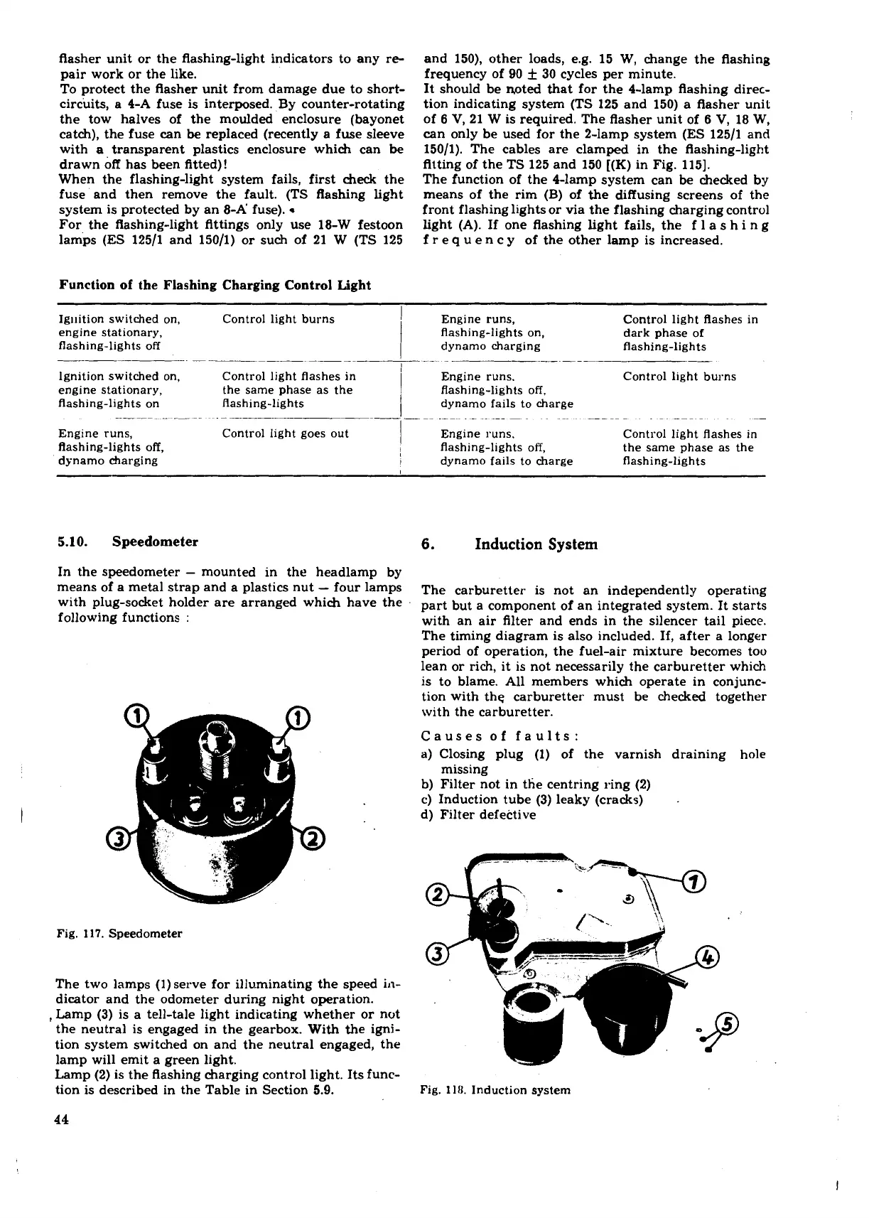
6.
Induction
System
The carburetter is not an independently operating
part but a component of an integrated system. It starts
with an air filter and ends in the silencer tail piece.
The timing diagram is also included. If, after a longer
period of operation, the fuel-air mixture becomes too
lean or rich, it is not necessarily the carburetter which
is to blame. All members which operate in conjunc-
tion with
the carburetter must be checked together
with the carburetter.
Causes of faults:
a)
Closing plug (1) of the varnish draining hole
missing
b) Filter not in the centring ring (2)
c) Induction tube (3) leaky (cracks)
.
d) Filter defective
Lamp (2) is the flashing charging control light. Its func-
tion is described in the Table in Section
5.9.
Fig.
11IJ.
Induction system
44