several jets of the same dimension in order to be in a
position to exchange them.
For needle jets, for example, the dimens according to
darwing
is
2.65+0.009
mm.
The types
ES
12511
-
15011 and the types before them
are provided with a small compression spring arranged
between twist-grip control member and cable control
retaining member.
In relaxed state, this spring is the stop for the idling
speed. In this position, the throttle valve is open for
a distance of about 1.5 mm.
Fig.
127.
Stop spring
'St"
=
Idling fuel supply with the motor cycle stationary or in
neutral posjtion
"A"
=
Switching off (throttle valve completely closed)
4
To stop the engine, the twist-grip must
be
closed over-
a
coming the resistance offered by the spring which is
,1
compressed to about
5
mm. Now the throttle valve
d
completely closes the air passage.
#
Please, notice
in
any ease:
A
proper carburetter tuning is always associated with
the correct ignition timing and contact breaker points
gap.
If, for example, the cam is out of true, the contact
breaker lifts two times per revolution. At high speeds.
a strong magnetic field cannot be built up in the igni-
tion coil
-
ignition fails. Then you may presume fuel
to lack; the dark appearance of the sparking-plug,
however, shows that there are ignition faults.
Similar
symptoms can be observed in the case of insufficient
contact-breaker points gap, retarded ignition, capacitcr
defects oc defects in the adjustable series resistor.
1.
Cycle
Parts
7.1.
Exhaust System
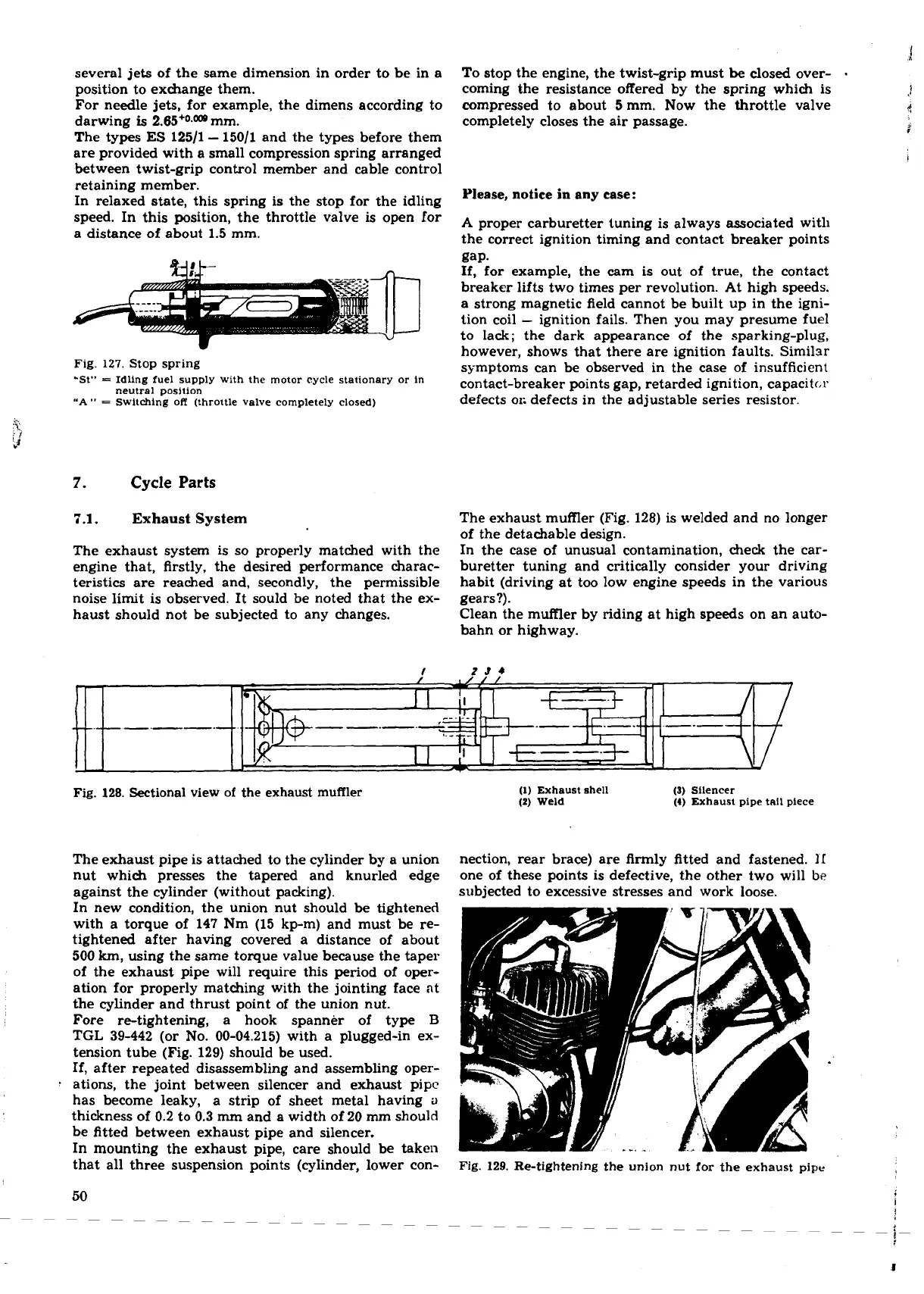
The exhaust muffler (Fig. 128) is welded and no longer
of the detachable design.
The exhaust system is so properly matched with the
In the case of unusual contamination, check the car-
engine that, firstly, the desired performance charac-
buretter tuning and critically consider your driving
teristics are reached and, secondly, the permissible
habit (driving at too low engine speeds in the various
noise limit is observed. It sould be noted that the ex- gears?).
haust should not be subjected to any changes.
Clean the muffler by riding at high speeds on an auto-
bahn or highway.
Fig.
128.
Sectional view of the exhaust muffler
(1)
Exhaust shell
(3)
Silencer
(2)
Weld
(4)
Exhaust pipe tall piece
The exhaust pipe is attached to the cylinder by a union
nection, rear brace) are firmly fitted and fastened.
I1
nut which presses the tapered and knurled edge one of these points is defective, the other two will
be
against the cylinder (without packing).
subjected to excessive stresses and work loose.
In new condition, the union nut should be tightened
with a torque of 147 Nm (15 kp-m) and must be re-
tightened after having covered a distance of about
500
km,
using the same torque value because the taper
of the exhaust pipe will require this period of oper-
ation for properly matching with the jointing face at
the cylinder and thrust point of the union nut.
Fore re-tightening, a hook spanner of type
B
TGL 39-442 (or No. 00-04.215) with a plugged-in ex-
tension tube (Fig. 129) should be used.
If, after repeated disassembling and assembling oper-
ations, the joint between silencer and exhaust pipc
has become leaky, a strip of sheet metal having
a
thickness of 0.2 to 0.3
mm
and a width of 20 mm should
be fitted between exhaust pipe and silencer.
In
mounting the exhaust pipe, care should be taken
that all three suspension points (cylinder, lower con-
Fig.
129.
Re-tightening the union nut for the exhaust
pipe
 Loading...
