5.6.
Ignition-light Switch
Dismantling the ignition-light switch is very simple.
Only one screw must be loosened which is arranged in
the front part of the headlamp in the centre, and
then
the ignition-light switch is drawn out of its guide to-
gether with the insulating foil and the fastener. Now
the ignition-light switch and the cable connections can
be easily inspected.
To
be
in a position tp plug the cables to the correct
lugs after a replacement of the ignition-light switch, the
various connections are once more clearly indentified
in Fig. 104.
5.7.
Headlamp
IT
the road is not sufficiently illuminated, check the
contact points in the leads to the bilux lamp because
dirty contacts cause consider-
able voltage drops!
Particular attention should be paid to the combined
dimmer switch at the left-hand side of the handlebars..
The contact screws must be properly tightened
-
b~t
care must be taken not to pinch off the cable ends
-
and then they must be protected against loosening by
a dot of paint.
It is advisable to protect the contact blades from cor-
rosion by the application of contact grease. Do not
forget to place the rubber backing between switch anc
holder at the handlebars (otherwise there is the ris!;
of accidental earth).
4
1
9
Fig.
105.
Connections
a1
the
drmmer
switch
1
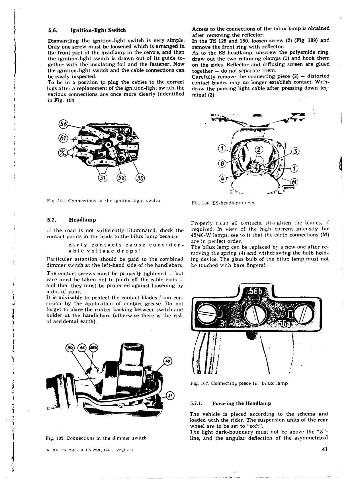
Access to the connections of the bilux lamp is obtained
after removing the reflector:
In the
TS
125 and 150, loosen screw (2) (Fig. 109) and
remove the front ring with reflector.
As to the
ES
headlamp, unscrew the polyamide ring,
draw out the two retaining clamps (1) and hook them
on the sides. Reflector and diffusing screen are glued
together
-
do not separate them.
Carefully remove the connecting piece (2)
-
distorted
conta~t blades may no longer establish contact. With-
draw the parking light cable after pressing down ter-
minal
(3).
Fig.
Ill(;.
ES-heatllanil~
cpen
P~wperly
clcan
all contacts. straighten the blades, if
required. In vie\v of the high current intensity for
45/40-W lan~ps. see
10
it that the earth connections
(M)
~
are in perfect order.
l
The bilux lamp can be replaced by a new one after re-
~
moving the spring
(4)
and withdrawing the bulb hold-
ing device. The glass bulb of the bilux lamp must not
be tcuched \vith bare fingers!
Fig.
107.
Connecting piece for bilux lamp
5.7.1.
Focusing
the Headlanlp
The vehicle is placed according to the schema and
loaded with the rider. The suspension units of the rear
wheel are to be set to "soft".
The light dark-boundary must not be above the
"Z"-
line, and the angular deflection of the asymmetrical
 Loading...
