7.12.2.
Banoval of
the
Shock-absorbers
The yellow colour dot means positive deviations, the
green colour dot negative deviations from the rated
Clamp the lower eye of the suspension unit in a vice.
value of damping power. In shodr-absorbera of a more
Press down the protective sleeve (8) and remove the
-nt design, the colour marking *yellow"
is
omitted
two ba*g-ring halves (1). Now, the Parts (811
(9).
for a positive deviation of the damping power; the
and (11) can be removed.
negative deviation will be marked "green" now as
before.
Always mate yellow with "yellow" or "green"
7.12.3.
Common Faults
in
Shock-absorbers
with "green".
l.
The shock-absorber
is
inactive, although there is no
visible oil leakage (foreign particles between the
diaphragms of the piston valve).
2.
The damping action fails to start smoothly but starts
jerkily. The spring-loaded suspension units are said
to "stamp" (insufficient amount of damping fluid
or bottom valve leakvh
"V
3.
Damping liquid leaks.
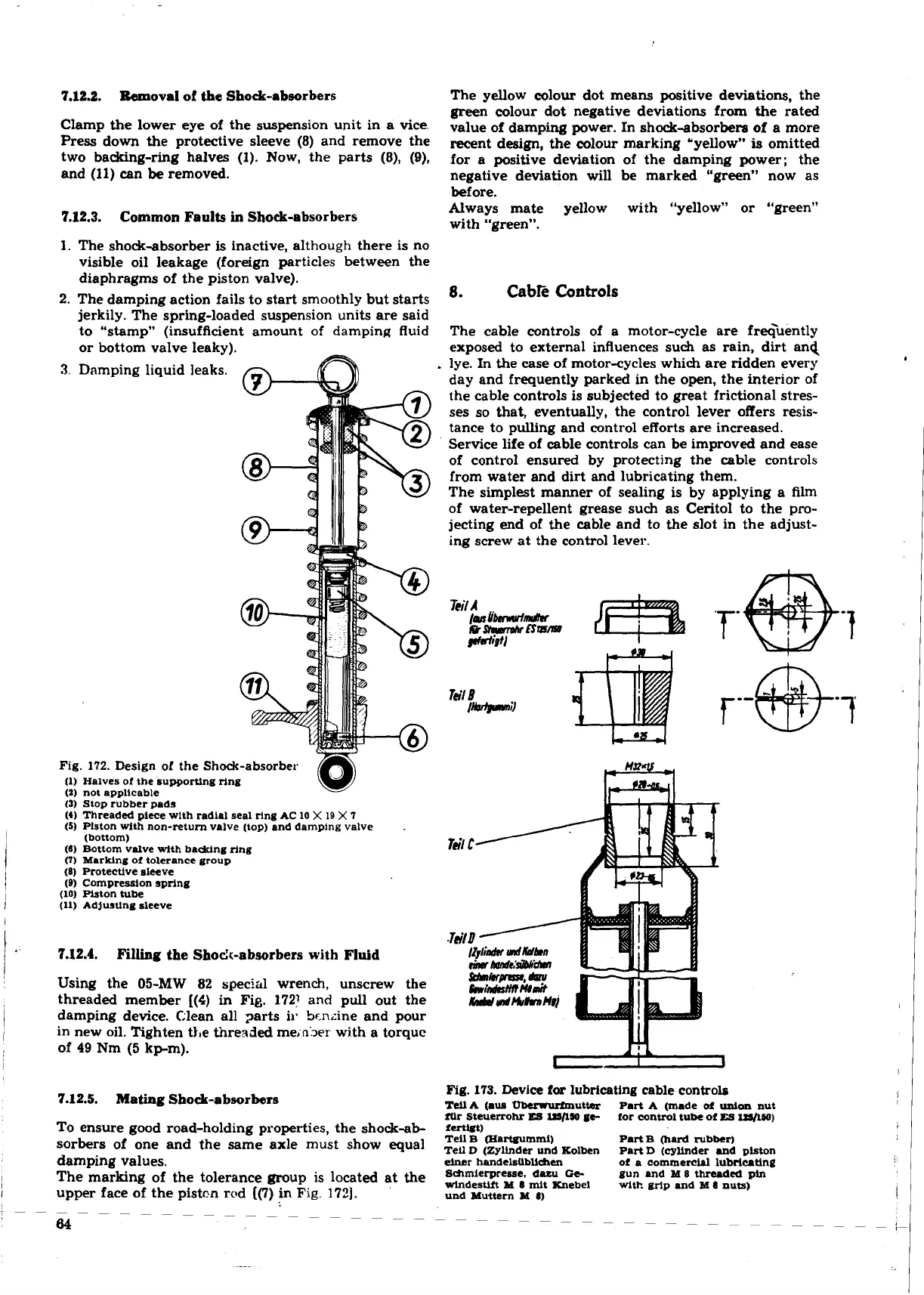
Fig.
172.
Design of the Shock-absorber
(1) Halves of the supporting ring
(2)
not aDDliCable
(3)
Stop ribber pads
(4)
Threaded piece wlth radial seal ring AC
10
X
l0
X
7
(5)
Piston with non-return valve (top) and damping valve
.
(bottom)
(6)
Bottom valve
wlth
badcing ring
(7)
Marking of tolerance group
(8) Protective sleeve
(B)
Compression spring
(10) Piston tube
(11)
Adjusting
sleeve
7.12.4.
Filling the Shock-absorbers with Fluid
Using the 05-MW
82
special wrench, unscrew the
threaded member
[(S)
in Fig. 1721
and
pull out the
damping device. Clean all parts ir Scn~ine and pour
in new oil. Tighten the thrended meinjer with a torque
of
49
Nm (5
kpm).
7.12.5.
Mating Shod-absorbers
To ensure good road-holding properties, the shock-ab-
sorbers of one and the same axle must show equal
damping values.
The marking of the tolerance group is located at the
upper face of the pistcn rcd ((7)
in
Fig.
172).
8.
Cabk
Controls
The cable controls of a motor-cycle are frGuently
exposed to external influences such as rain, dirt and
lye. In the case of motor-cycles which are ridden every
day and frequently parked in the open, the interior of
the cable controls is subjected to great frictional stres-
ses so that, eventually, the control lever offers resis-
tance to pulling and control efforts are increased.
Service life of cable controls can be improved and ease
of control ensured by protecting the cable controls
from water and dirt and lubricating them.
The simplest manner of sealing is by applying a film
of water-repellent grease such as Ceritol to the
pro-
jecting end of the cable and to the slot in the adjust-
ing screw at the control lever.
Fig.
173.
Device
for
lubricating cable controls
Tell
A
(.us
-utter
Part
A
(made
of
union
nut
fur Steuerrohr
m
=/l50
ge-
for control tube ot
ES
IH/MO)
fmut)
Tell B (Hartpummi) Part B (hard rubber)
TeU
D
(Zyllnder und Kolben
Part
D
(cylinder and piston
einer
handelsublichen
of a cornmerctpl
lubclcnting
Srhmietpreaae. dau
Ce-
gun and
M
8 threaded pin
wlndestlft
M
8
mit Knebel
with grlp and
M
8
nuts)
und Muttern M
8)
 Loading...
