First insert short pjeces of tubes, then larger ones. Fix
the swing arm by means of the 05-MW 26-4 centring
bolt (1) and push the new pin in place from the left-
hand side (see arrow). Make sure the indicated sur-
faces (see arrow in Fig. 135) of the bearing pin are
located below the retaining screws of the front carrier,
otherwise the next dismantling operation will meet
with difficulties.
The end clearance is balanced by means of the lock
nuts; the swing arm must slide down by virtue of its
own weight. Tighten the retaining screws and lock
them by means of nuts.
Fig.
134.
Replacing the front swing-arm bearing bolt
supply of oil.
In order to ensure a certain permanent lubrication,
the use of molybdenum sulphide suspensate is recom-
mended.
Fig.
135.
Swing-arm bearing bolt
(See
Flg.
136.
page'%)
v.2.2.
TS
125
and
TS
150
7.2.2.1.
Steering Bearing
The ball bearings are driven into the frame in the
following manner:
1. Press th,c lowcl. txiaring down to the stop, using the
intermediate
ring
54
mm in diameter
X
20 mm, so
that pressurc3 is exerted on the outer ring;
2. Insert the
disl;~ncc sleevc:
3. Press thc upper
bearing
down until its inner ring
contacts thc distance sleeve; in this operation take
care that
the,
distance ring, 54mm in diameter
X
40 mm.
ih
placed under the lower bearing in
order thal the lowc~ bearing is not pressed out;
and thcm ~~lso
cw~l
plx,ssure on the intermediate
ring,
54
mm
in d~;~rn~~t~~r
X
20 mm, in order that
the innc.1 and
outer
rings of the upper bearing prop-
erly cont~cct
thc~ir
miltlng parts.
Since thc stc~~rlng components are mounted on ball
bearings, no
;rdjilst~ng opc'rat ions are required. The
steering bci~r~ii:: 1s in
pc~fcw
\\.orking condition if the
ball bearing:;
lia\.~~
a
propc~ press fit and the covering
nut is propcrly tightcmcd. The specified torque for this
operation is
147
Nm
(15
kp-m) (use a box spanner or
socket \v~.cwc.li
o!ily).
Tlio screwed joint need not be
locked.
I
The two bearing points of the front and rear swing-
arm bearing pins are provided with two rubber pack-
ing~ each to prevent the lubricating oil (only use
en-
gine oil or gear oil) from leaking away sidewards.
For fitting the packing rings, use the 13-MV 26-4 tap-
ered sleeve to prevent damage.
Bearing pins lubricated with grease by mistake must
be taken out and cleaned thoroughly.
Only use g e a
r
o
i
l because of the narrow fit (cf.
Section 2.4.). Use perfectly tight lubricating nipples;
the bearing pins must be provided with an ample
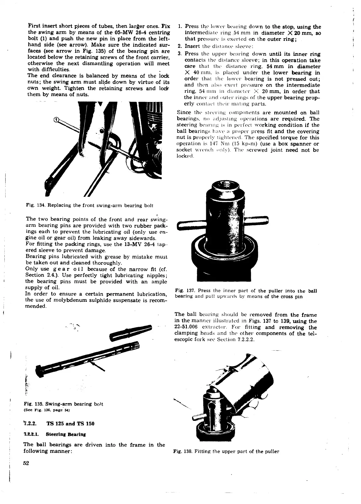
Fig.
137.
Press the inner part of the puller into the
ball
bearing and
pull
up\v:~rds
by
means of the
cross
pin
The ball benling should be removed from the frame
in the
manner illust~xtcd in Figs. 137 to 139, using the
22-51.006 ex
t
rnctor.
For
fitting and removing the
clamping heads and
the.
other components of the tei-
escopic fork sec Section 7.2.2.2.
Fig.
138.
Fitting
the
upper part of the puller
 Loading...
