7.2.2.2.
Telescopic Fork
(see Fig.
136)
The front part of the machine is disassembled into its
main components as follows:
1. Remove front wheel and front wheel mudguard.
2.
Remove handlebars and place them on the fuel tank
(place a protcctivc cloth underneath).
3. Loosen cable connections and speedometer spindle
from headlamp (mark thc plug-in type connections
for identification) and dismantle head-lamp.
4. Loosen scre\v plugs and covering nut.
5. Remove thc uppcr clamping head (drive upwards
by means of
a
rubbcr mallet) together with head-
lamp holdcl and rubbcr pad for headlamp holder.
6.
U'ithdraw thr lowcr clanlping head together with
thc guide tubes do\\n\\i~~.ds. tapping the control
tube by means of a ~.ubb~ mallet. if required, (note
that thr guidr tubes should remain clamped in the
lo\vcl- clanlping hcnd. unlcss thr telescopic uni!s
ha\^
to br disn~;~ntled).
Fig.
139.
ScreLving
in
the sc~.t.\\', tightening and in this
way
pulling the bearing out of the frame
Mounting is to bc done in the inverse order of the
disassembling opclxtions.
The screwed joints should be tightened in the follow-
ing order:
1. Covering nut.
2.
Screw plugs for telescopic units, applying
a
thin
film of the "Chcmisol 1405" adhesive lacquer (manu-
facturer:
VEB
Schuh-Chemie, Erfurt) to the thread
of the screw plug? for sealing them.
..
("Chemisol" is made on the basis of synthetic caoa-
tchouc, viscosity: 30 s run out time of 50 m1 with
a
5-mm jet. In countries other than the GDR, an ad-
hesive lacquer of similar properties should be used
for sealing.)
Torque: 147 Nm (15 kp-m).
3. Clamping screws at the lower clamping head
-
torque 34.3 to 44.1 Nm (3.5 to 4.5 kp-m).
4. Nut of the knockout spindle; then, while the motor-
cycle is stationary, vigorously more the system
several times through the full travel from bump to
rebound (while the mudguard screws are still loose)
to ensure that'the knockout spindle assumes proper
position in the opening provided for the spindle,
the spindle bush, where a sliding fit must be ensur-
ed; if necessary, finish ream the left-hand spindle
receiving bush to
a
size of 20
mm
in
diameter.
5. Clamping screw for knockout spindle.
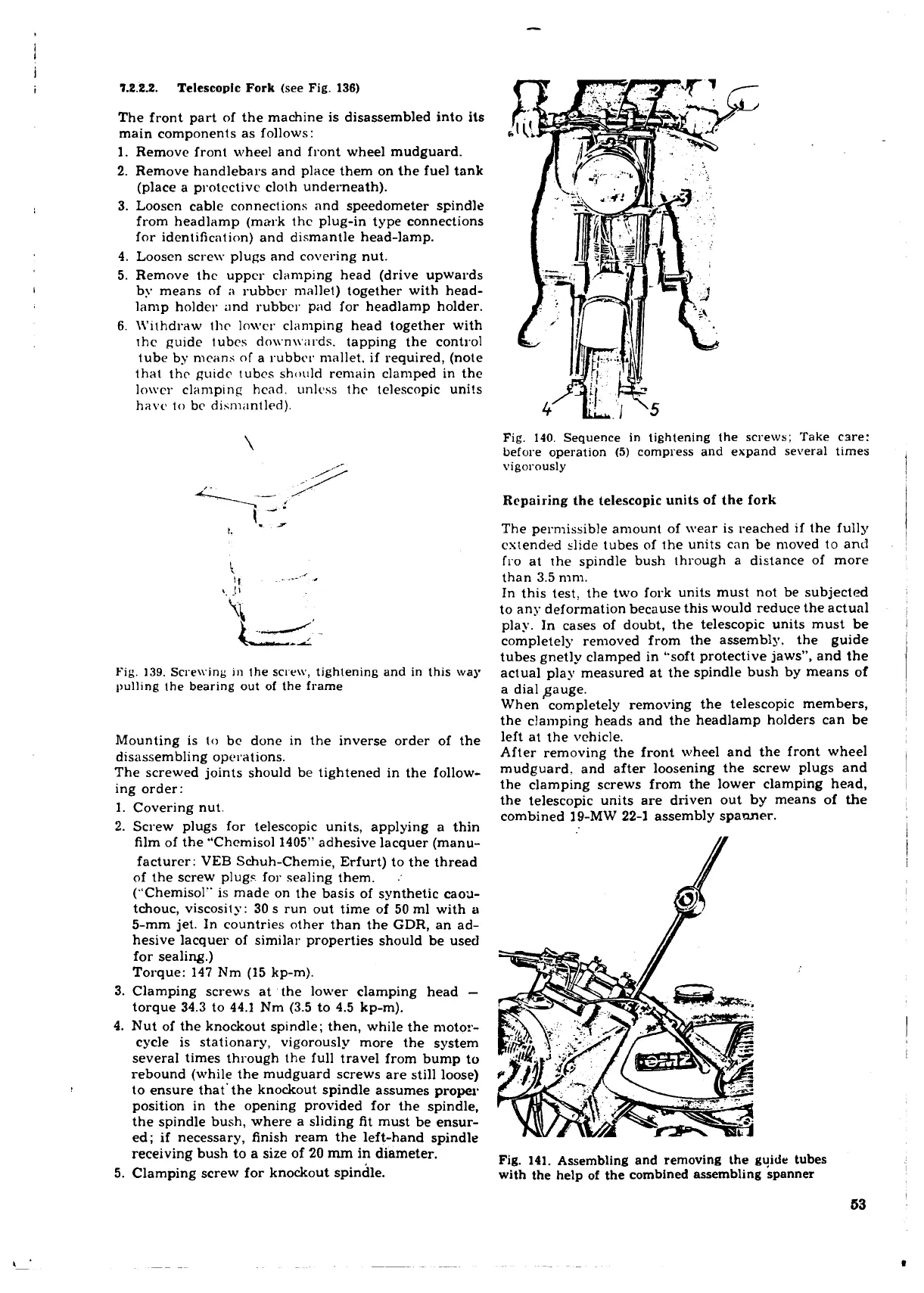
Fig.
140.
Sequence in tightening the screws; Take csre:
before operation
(5)
compress and expand several times
vigorously
Repairing the telescopic units of the fork
The permissible amount of wear is reached if the fully
cstended dide tubes of the units can be moved to and
fro at the spindle bush through a distance of more
than 3.5 mm.
In this test. the two fork units must not be subjected
to any deformation because this would reduce the actual
play. In cases of doubt, the telescopic units must be
completely removed from the assembly. the guide
tubes
gnetly clamped in "soft protective jaws", and the
actual play measured at the spindle bush by means of
a dial Sauge.
When completely removing the telescopic members,
the clamping heads and the headlamp holders can be
left at the vehicle.
After removing the front wheel and the front wheel
mudguard. and after loosening the screw plugs and
the clamping screws from the lower clamping head,
the telescopic units are driven out by means of the
combined 19-MW 22-1 assembly
spanner.
Fig.
141.
Assembling and removing the gyide tubes
with the help of the combined assembling spanner
 Loading...
