Fig.
123.
Needle holder
Fig.
124.
Partial load
needle with needle
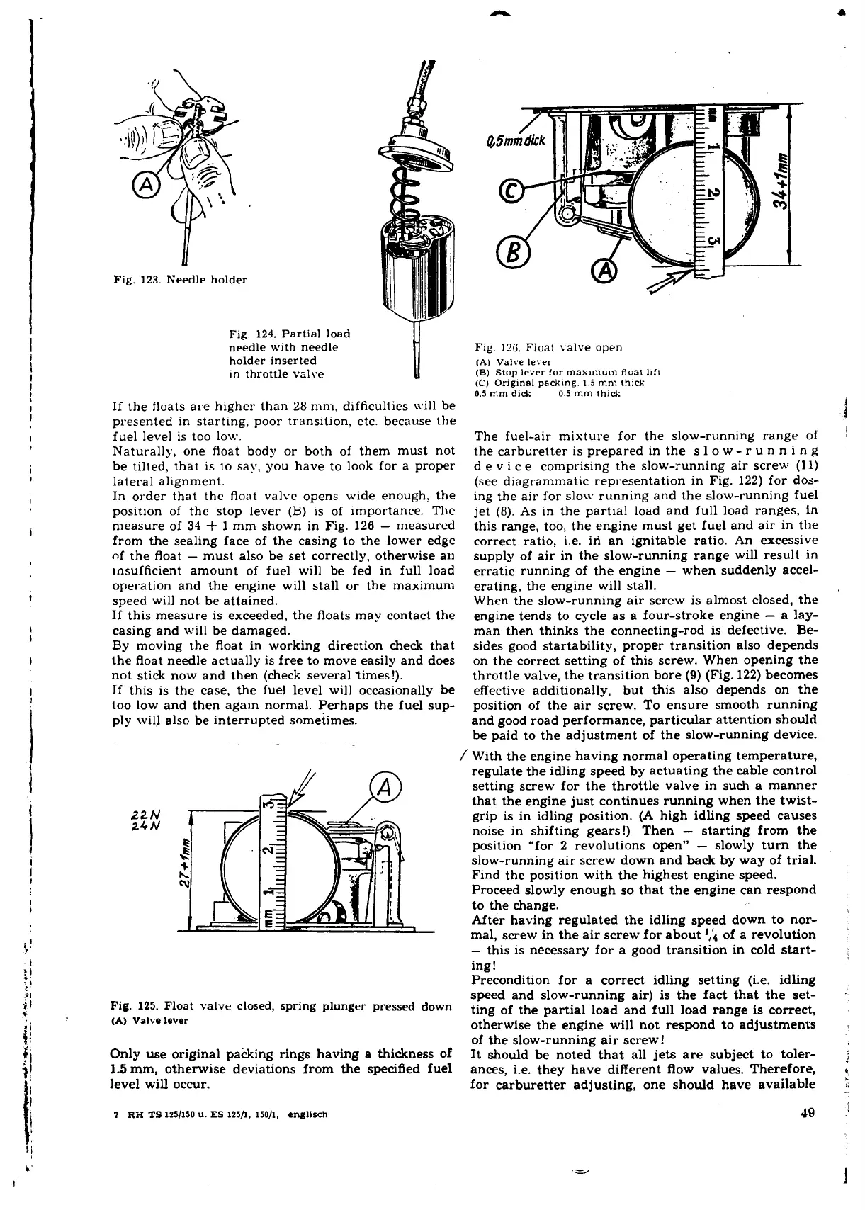
Fig.
126.
Float
valve
open
holder inserted
(A)
valve
lever
in
throttle valve
(B) stop
lever
for
rnaxi~num
float
II~I
(C)
Original
padc~ng.
1.5
mm
thick
0.5
mm
dick
0.5
mm
thick
If the floats are higher than 28 mm, difficulties will be
presented in starting, poor transition. etc. because the
l
fuel level is too low.
The fuel-air mixture for the slow-running range 01
i
Naturally, one float body or both of them must not the carburetter is prepared in the
S
l o
W
-
r
U
n n i n g
be tilted, that is to say, you have to look for a proper d e v i c e comprising the slow-running air screw
(11)
lateral alignment.
(see diagrammatic representation in Fig. 122) for dos-
In order that the float valve opens wide enough, the
ing the air for slow running and the slow-running fuel
position of
thc stop lever
(B)
is
of importance. Tlw
jet (8). As in the partial load and full load ranges, in
measure of
34
+
1 mm shown in Fig. 126
-
measured
this range, too, the engine must get fuel and air in the
from the sealing face of the casing to the lower edge
correct ratio, i.e. iri an ignitable ratio. An excessive
of the float
-
must also be set correctly, otherwise an
supply of air in the slow-running range will result in
insufficient amount of fuel will be fed in full load erratic running of the engine
-
when suddenly accel-
operation and the engine will stall or the maximum erating, the engine will stall.
speed will not be attained.
When the slow-running air screw is almost closed, the
If this measure is exceeded, the floats may contact the engine tends to cycle as a four-stroke engine
-
a lay-
casing and will be damaged.
man then thinks the connecting-rod is defective. Be-
By moving the float in working direction check that sides good startability, proper transition also depends
the float needle actually is free to move easily and does on the correct setting of this screw. When opening the
not stick now and then (check several times!).
throttle valve, the transition bore
(9)
(Fig. 122) becomes
If this is the case, the fuel level will occasionally be effective additionally, but this also depends on the
too low and then again normal. Perhaps the fuel sup-
position of the air screw. To ensure smooth running
ply will also be interrupted sometimes. and good road performance, particular attention should
be paid to the adjustment of the slow-running device.
/
With the engine having normal operating temperature,
regulate the idling speed by actuating the cable control
setting screw for the throttle valve in such a manner
that the engine just continues running when the twist-
22
N
grip is in idling position. (A high idling speed causes
24
N
noise in shifting gears!) Then
-
starting from the
position "for 2 revolutions open"
-
slowly turn the
slow-running air screw down and back by way of trial.
Find the position with the highest engine speed.
Proceed slowly enough so that the engine can respond
to the change.
l
After having regulated the idling speed down to nor-
mal, screw in the air screw for about
',;
of a revolution
-
this is necessary for a good transition in cold start-
ing!
Precondition for a correct idling setting (i.e. idling
speed and slow-running air) is the fact that the set-
~ig.
125.
~loat valve closed, spring plunger pressed down
ting
of
the partial load and full load range is correct,
(A)
Valve
lever
otherwise the engine will not respond to adjustments
of the slow-running air screw!
Only use original pakking rings having a thickness of
It should be noted that all jets are subject to toler-
f
1.5
mm, otherwise deviations from the specified fuel
ances, i.e. they have different flow values. Therefore,
e
level will occur.
for carburetter adjusting, one should have available
7
RH
TS
1251150
U.
ES
125/1.
150/1,
englisch
 Loading...
