Disks with frictional lining:
Thickness, new
3.4
f
0.1
mm
maximum amount of wear
-
0.2
mm
Compression springs:
Length, slack 49 mm
spring power
157
N
(16 kp) with a
mounting length of 31.5 mm
Fig.
60.
Clutch dismantled
(I)
Holding disk,
(2)
Spring plate,
(3)
Pressure pin
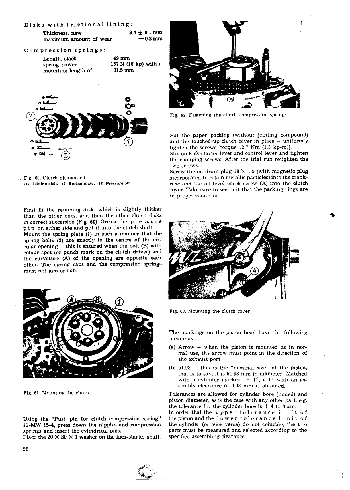
Fig.
62.
Fastening the clutch compression
springs
Put the paper packing (without jointing compound)
and the touched-up clutch cover in place
-
uniformly
tighten the screws [torque 12.7 Nm (1.3 kp-m)].
Slip on kick-starter lever and control lever and tighten
the clamping screws. After the trial run retighten the
two screws.
Screw the oil drain plug 18
X
1.5 (with magnetic plug
incorporated to retain metallic particles) into the crank-
case and the oil-level check screw (A) into the clutch
cover. Take care to see to it that the packing rings are
in proper condition.
First fit the retaining disk, which is slightly thicker
than the other ones, and then the other clutch disks
in correct succession (Fig. 60). Grease the p
r e ss
U
r e
p in on either side and put it into the clutch shaft.
Mount the spring plate (1) in such a manner that the
spring bolts
(2)
are exactly in the centre of the cir-
cular opening
-
this is ensured when the bolt
(B)
with
colour spot (or punch mark on the clutch driver) and
the curvature
(A)
of the opening are opposite each
other. The spring caps and the compression springs
must not jam or rub.
Fig.
63.
Mounting th.e clutch cover
The markings on the piston head have the following
meanings
:
(a) Arrow
-
when the piston is mounted as in nor-
mal use, th- arrow must point in the direction of
the exhaust port.
(b) 51.98
-
this is the "nominal size" of the piston,
that is to say, it is 51.98 mm in diameter. Matched
with a
cylinder marked
"+
l", a fit L\-ith an as-
sembly clearance of
0.03
mm is obtained.
Fig.
61.
Mounting the clutch
Using the "Push pin for clutch compression spring"
11-MW 15-4, press down the nipples and compression
springs and insert the cylindrical pins.
Place the
20
X
30
X
1
washer on the kick-starter shaft.
Tolerances are allowed for cylinder bore (honed) and
piston diameter. as is the case with any other part, e.g.
the tolerance for the cylinder bore is
+
4
to
6
pm.
Inorder that the upper tolerance
i.
't of
thepistonandthe lower tolerance limit of
the cylinder (or vice versa) do not coincide, the
t,
a
parts must be measured and selected according to the
specified assembling clearance.
 Loading...
