Withdraw the piston support.
During this operation, retain the cylinder with one
hand so that it cannot go down.
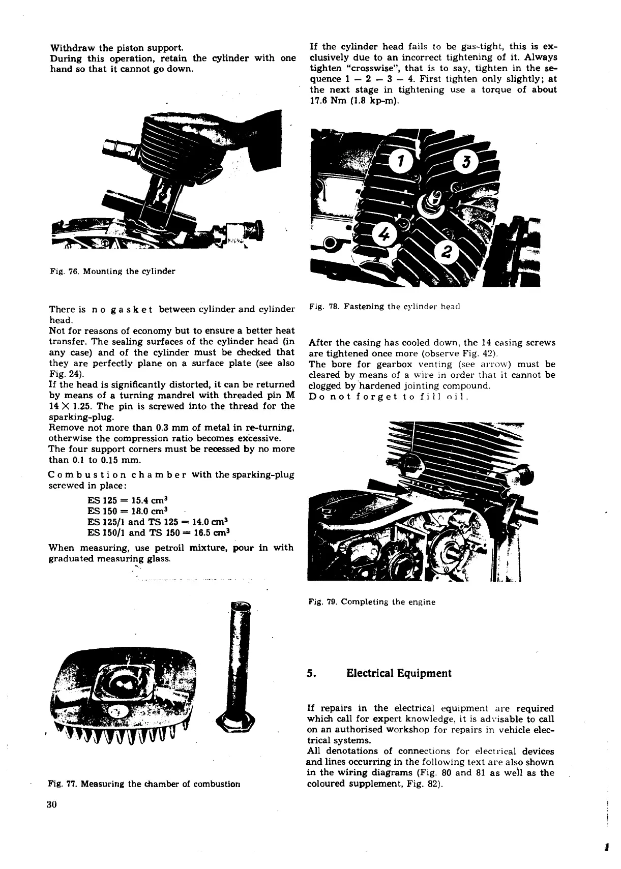
If the cylinder head fails to be gas-tight, this is ex-
clusively due to an incorrect tightening of it. Always
tighten "crosswise", that is to say, tighten in the se-
quence
1
-
2
-
3
-
4.
First tighten only slightly; at
the next stage in tightening use a torque of about
17.6
Nm
(1.8
kp-m).
Fig.
56.
Mounting the cylinder
There is n o g a
S
k e t between cylinder and cylinder
head.
Not for reasons of economy but to ensure a better heat
transfer. The sealing surfaces of the cylinder head (in
any case) and of the cylinder must be checked that
they are perfectly plane on a surface plate (see also
Fig.
24).
If the head is significantly distorted, it can be returned
by means of a turning mandrel with threaded pin
M
14
X
1.25.
The pin is screwed into the thread for the
Fig.
78.
Fastening the cylinder he~tl
After the casing has cooled down, the
14
casing screws
are tightened once more (observe Fig.
47).
The bore for gearbox venting (see arrow) must be
cleared by means of a wire in order that it cannot be
clogged by 'hardened jointing compound.
Do not forget to fill oil.
sparking-plug.
Remove not more than
0.3
mm of metal in re-turning,
otherwise the compression ratio becomes excessive.
The four support corners must
be
recessed by no more
than
0.1
to
0.15
mm.
C
o m b
U
s t i o n c h a
m
b e r with the sparking-plug
screwed in place:
ES
125
=
15.4
cm3
ES
150
=
18.0
cm3
.
ES
12511
and
TS
125
=
14.0 cm3
ES
15011
and
TS
150
=
16.5 cm3
When measuring, use petroil mixture, pour in with
graduated measuring glass.
Fig.
79.
Completing the engine
5.
Electrical Equipment
Fig.
77.
Measuring the chamber of combustion
30
If repairs in the electrical equipment are required
which call for expert knowledge, it is advisable to call
on an authorised workshop for repairs in vehicle elec-
trical systems.
All denotations of connections for electrical devices
and lines occurring in the following text are also shown
in the wiring diagrams (Fig.
80
and
81
as weh as the
coloured supplement, Fig.
82).
 Loading...
