Fig.
119.
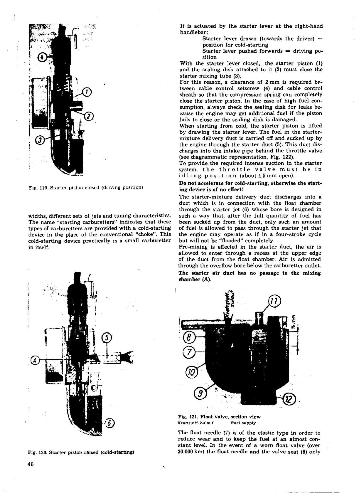
Starter piston closed (driving position)
widths, different sets of jets and tuning characteristics.
The name "starting carburetters" indicates that these
types of carburetters are provided with a cold-starting
device in the place of the conventional "choke". This
cold-starting device practically is a small carburetter
in itself.
Fig.
120.
Starter piston raised (cold-starting)
46
It is actuated by the starter lever at the right-hand
handlebar:
Starter lever drawn (towards the driver)
=
position for cold-starting
Starter lever pushed forwards
=
driving po-
sition
With the starter lever closed, the starter piston (1)
and the sealing disk attached to it (2) must close the
starter mixing tube (3).
For this reason, a clearance of 2 mm is required be-
tween cable control setscrew
(4)
and cable control
sheath so that the compression spring can completely
close the starter piston. In the case of high fuel con-
sumption, always check the sealing disk for leaks be-
cause the engine may get additional fuel if the piston
fails to close or the sealing disk is damaged.
When starting from cold, the starter piston is lifted
by drawing the starter lever. The fuel in the
starter-
mixture delivery duct is carried off and sucked up by
the engine through the starter duct (5). This duct dis-
charges into the intake pipe behind the throttle valve
(see diagrammatic representation, Fig. 122).
To provide the required intense suction in the starter
system, the throttle valve must be in
i d l i n g p o s i t i o
n
(about 1.5 mm open).
Do not accelerate for cold-starting, otherwise the start-
ing device is of no effect!
The starter-mixture delivery duct discharges into
a
duct which is in connection with the float chamber
through the starter jet
(6)
whose bore is designed in
such a way that, after the full quantity of fuel has
been sucked up from the duct, only such an amount
of fuel is allowed to pass through the starter jet that
the engine may operate as if in a four-stroke cycle
but will not be "flooded" completely.
Pre-mixing is effected in the starter duct, the air is
allowed to enter through a recess at the upper edge
of the duct from the float chamber. Air
is
admitted
through the overflow bore below the carburetter outlet.
The starter air duct has no passage to the mixing
chamber
(A).
Fig.
121.
Float valve, section view
Kroltstoff-Zulauf Fuel supply
The float needle
(7)
is of the elastic type in order to
reduce wear and to keep the fuel at an almost con-
stant level.
In
the event of a worn float valve (over
.
30.000 km) the float needle and the valve seat
(8)
only
 Loading...
