1.
Technical Data
1.1.
Engine
Connecting-rod bearing
Crankshaft main bearing
1.8.
Capacities
Telescopic fork
2.
Fuel, Lubricants and Fluids
.
2.2.
Engine
Oil
The two-stroke engine oil is added to the fuel in
a
mixing ratio of
1
:50
This means that, for example, 0.20 1 of engine oil are
added to 10 1 of fuel.
2.5.
Damping
Fluid
The shock-absorber oil must be mixed with molyb-
denum disulfide oil suspension (Molykote, Fimol or
the like) in the mixing ratio of 45
:
l.
3.
Disassembly
of
the Engine
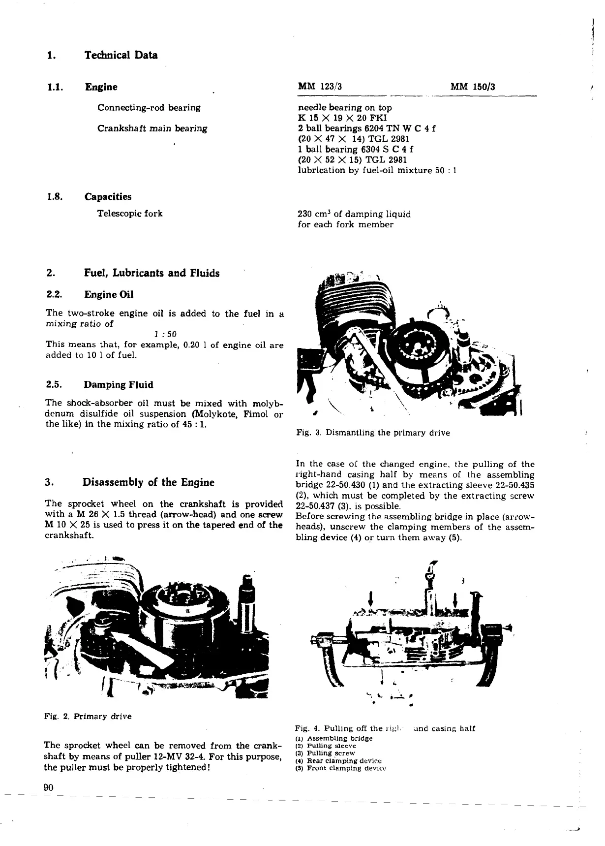
The sprocket wheel on the crankshaft is provided
with a
M
26
X
1.5 thread (arrow-head) and one screw
M
10
X
25 is used to press it on the tapered end of the
crankshaft.
Fig.
2.
Primary
drive
The sprocket wheel can be removed from the crank-
shaft
by
means of puller 12-MV
32-4.
For this purpose,
the puller must be properly tightened!
MM
123!3
.-
MM
15013
needle bearing on top
K
15
X
19
X
20 FKI
2
ball bearings 6204 TN
W
C
4 f
(20
X
47
X
14)
TGL
2981
1 ball bearing 6304
S
C
4
f
(20
X
52
X
15)
TGL
2981
lubrication by fuel-oil mixture 50
:
1
230 cm3 of damping liquid
for each fork member
Fig.
3.
Dismantling the primary drive
In the case of the changed engine. the pulling of the
right-hand casing half by means of the assembling
bridge 22-50.430 (1) and the extracting sleeve 22-50.435
(21,
which must be completed by the extracting screw
22-50.437 (3). is possible.
Before screwing the assembling bridge in place (alx-ow-
heads), unscrew the clamping members of the assem-
bling device (4) or turn them away
(5).
Fig.
4.
Pulling
off
the
rig!,
and
casing
half
(1) Assembling bridge
(2)
Pulling sleeve
(3)
Pulling screw
(4)
Rear
clamping device
(5)
Front clamping device
 Loading...
