16 of 26
GT 710-8710 OPUS Low Energy Swing Doors Quick Set-Up and Parts Guide www.NabcoEntrances.com
P/N C-00178 Rev 12-20-17
DN 1375
21” Track
Wheeled Roller
Wheeled Roller
Inswing Arm
“0” Reveal
12-1/4” Track
Figure 24 Insert the Swing Arm into the Track
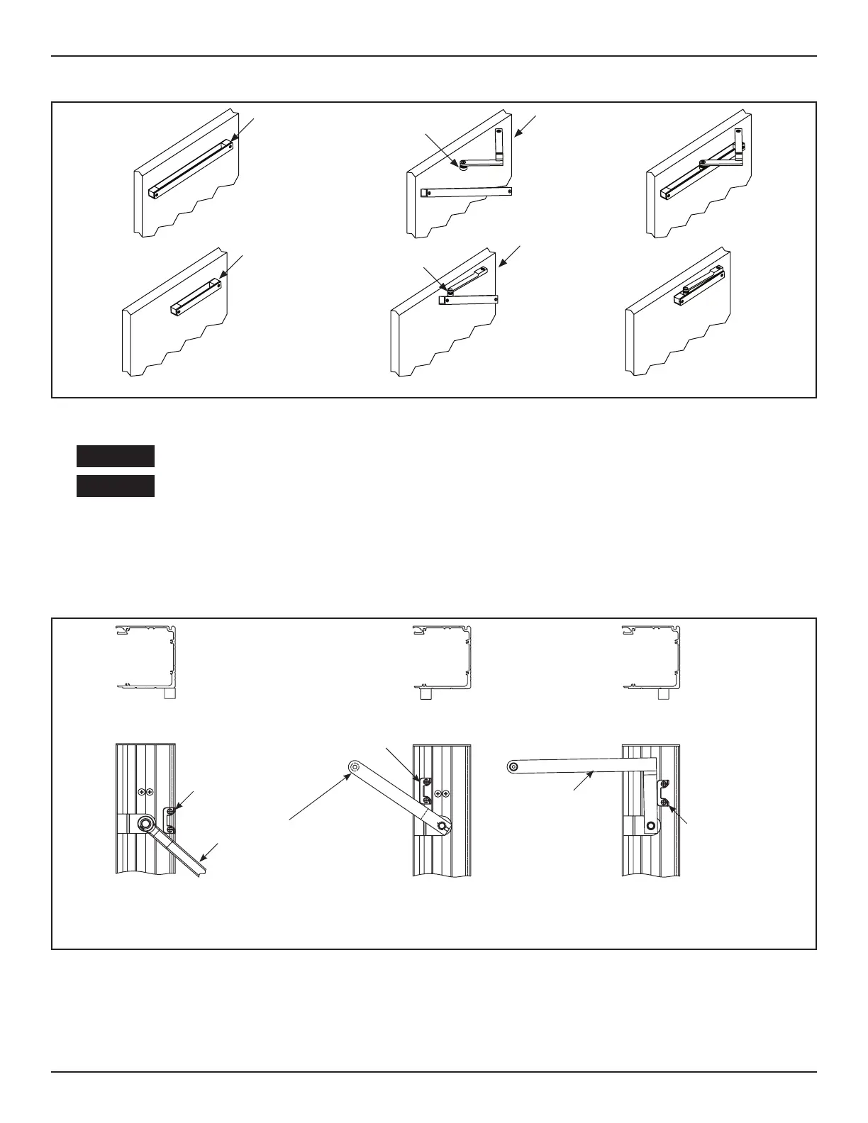
CHAPTER 8: INSTALL THE ARM STOP
Power must be turned OFF while installing the Arm Stop.
Do Not drill screw holes for the Arm Stop into the Motor/Operator!!!
DN 1064
INSWING ARM
0 1/4” REVEAL
INSWING ARM
GREATER THAN
1/4” REVEAL
OUTSWING ARM
Outswing
8400
8500
8600
8710
Inswing
8400
8500
8600
8710
Inswing
8400
8500
8600
8710
***CAUTION***
Remove Operator
before drilling holes
for Arm Stop
***CAUTION***
Remove Operator
before drilling holes
for Arm Stop
***CAUTION***
Remove Operator
before drilling holes
for Arm Stop
Posi on Arm Stop as shown.
Drill (2) 7/32” diameter holes.
Fasten with (2) 1/4-20x1-1/2” screws.
Posi on of Swing Arm
when Swing door is
opened to desired posi on.
Posi on Arm Stop as shown.
Drill (2) 7/32” diameter holes.
Fasten with (2) 1/4-20x1-1/2” screws.
Posi on Arm Stop as shown.
Drill (2) 7/32” diameter holes.
Fasten with (2) 1/4-20x1-1/2” screws.
Posi on of Swing Arm
when Swing door is
opened to desired posi on.
Figure 25 Arm Stop Configurations