Page 13 www.NabcoEntrances.com 5-7-10
Nabco Multi-Module
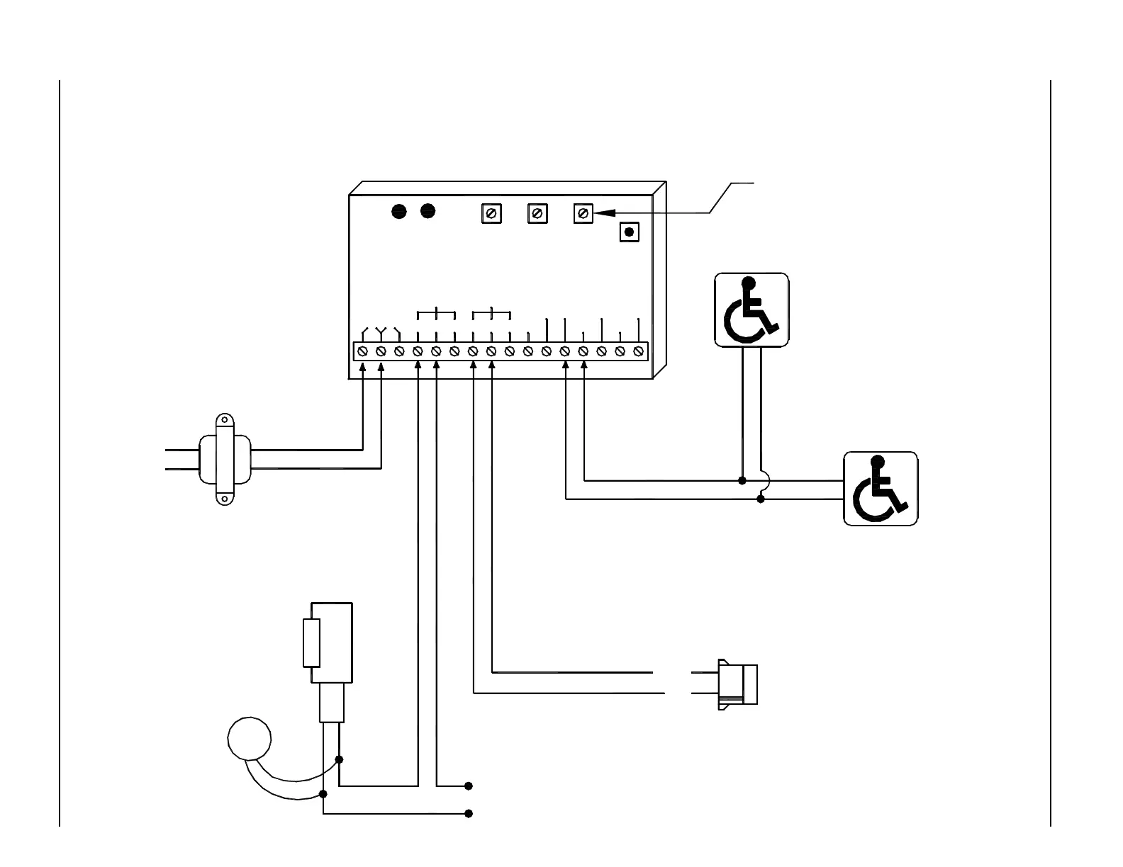
MODE 3 - RATCHET OR LATCHING OPERATION DIAGRAM - ANALOG CONTROL
Mode 3 not required with Magnum control - Magnum control includes this feature
Transformer
P/N 14-2101
24 VAC
24 VAC120 VAC
If magnetic
lock or fail safe
strike used,
connect lock
wires to COM
and N.C.
terminals of
Multi-Module
Exterior Switch
Normally Open - Dry Contacts
ELECTRIC
STRIKE
strike voltage)
(To match
TVS
STRIKE POWER
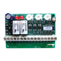
iti-200S
RELAY2RELAY1
WET3WET2
DRY2DRY1
DRY
COMCOM
WET
WET1N.O. COM N.C.N.C.COMN.O.
12V24V
LED LED
RL2RL1
RELAY 1
ON TIME
DOO
(DELAY
ON
OPERATE)
RELAY 2
RELAY 2
ON TIME
SW 1
MODE
SWITCH
DN 0302
Interior Switch
Normally Open - Dry Contacts
NOTES:
1. Pushing either switch once
unlocks and opens door.
2. Door will remain open until
switch is pushed again.
3. This mode only used with
Analog control. Magnum and
U series controls have this
feature built in.
4. A black circle indicates a
wire connection.
5. Power supply inputs not
polarity sensitive.
This potentiometer has no effect
RED
BLACK
Activation Connector on Analog Control
Not polarity sensitive.
Voltage Suppressor
directly to strike.
(supplied)
Connect Transient